CMP242 Charging arrangements for interlinked offshore transmission solutions connecting to a single onshore substation
|
|
|
- Ruth Lydia Banks
- 5 years ago
- Views:
Transcription


1 Stage 03: Workgroup Report Connection and Use of System Code (CUSC) CMP242 Charging arrangements for interlinked offshore transmission solutions connecting to a single onshore substation CMP242 aims to ensure that there are appropriate charging arrangements for offshore transmission network where two offshore substations, connected to the same onshore substation, have a transmission connection (interlink) between them offshore What stage is this document at? Initial Written Assessment Workgroup Consultation Workgroup Report Code Administrator Consultation Draft CUSC Modification Report Final CUSC Modification Report Published on: 22 October 2015 This document contains the discussion and conclusions of the Workgroup which formed in April 2015 to develop and assess the proposal. The Workgroup concludes: That the original, WACM1 and WACM2 all better facilitate the CUSC objectives than the CUSC baseline. Half of the Workgroup concluded that the Original Proposal best facilitates the CUSC objectives and should be implemented. Half of the Workgroup concluded that WACM1 best facilitates the CUSC objectives and should be implemented. High Impact: Offshore Generators Low Impact: All other parties liable for TNUoS 1
2 Contents 1 Summary Background Summary of Workgroup Discussions Original Proposal Workgroup Alternatives Impact and Assessment Proposed Implementation and Transition Workgroup Consultation Responses Views...40 Annex 1 CMP242 CUSC Modification Proposal Form...44 Annex 2 CMP242 Terms of Reference...49 Annex 3 Workgroup attendance register...53 Annex 4 Workgroup Consultation Responses...54 Annex 5 Guide to TNUoS Charging Methodology for Offshore Generation in GB...73 Annex 6 Mathematical Definitions of the Apportionment Options from Workgroup Consultation...79 Annex 7 - Updated Offshore Local Security Factor Mathematical Note...80 Annex 8 Draft Legal Text...81 Any Questions? Contact: Jade Clarke Code Administrator Jade.Clarke@ nationalgrid.com Proposer: Paul Wakeley National Grid Paul.Wakeley@ nationalgrid.com About this document This is the final Workgroup Report, which includes the deliberations of the Workgroup, responses from the Workgroup Consultation and the final conclusions of the Workgroup. Document Control Version Date Author Change Reference October 2015 Code Administrator Workgroup Report to CUSC Panel 2
3 1 Summary 1.1 CMP242 was proposed by National Grid Electricity Transmission plc and submitted to the CUSC Modifications Panel for their consideration on 27 th March The CMP242 proposal aims to ensure that there are appropriate charging arrangements within the CUSC for offshore transmission networks that link two, or more, offshore substations (used by offshore generators) which are connected to the same onshore substation; i.e. are interlinked offshore. The interlinks allow generators connected to either offshore substation to export some (or all) of their output to shore via either generator s circuits to shore (depending on the capacity available on the circuits and interlink). At present the charging methodology for offshore transmission considers only radial circuits to shore and therefore does not take account of any interlinks that may be built. This modification does not cover the situation where increased onshore capacity would be provided or where the interlink would influence the design of onshore reinforcement works; i.e. an integrated offshore network. 1.3 Following the workgroup discussions, as summarised in this report, the Original Proposal and two Workgroup Alternative CUSC Modifications (WACMs) were proposed: a. Original Proposal: The costs of the interlink circuit are shared between the generators, based on a formula representing the opportunity each generator has to use the interlink in the event of a single fault; b. WACM1: The formula is the same as the Original Proposal, however, there is an alternative for parties to negotiate how the costs of the interlink circuit are shared between the generators to take in to account other factors. c. WACM2: The costs of the interlink circuit are shared between the generators as determined by negotiation between the generators only. 1.4 At the final Workgroup meeting, Workgroup members voted on the Original Proposal and the two WACMs: Half of the Workgroup concluded that the Original Proposal better facilitates the CUSC objectives and should be implemented. Half of the Workgroup concluded that WACM1 better facilitates the CUSC objectives and should be implemented. 1.5 The Workgroup Report and supporting material has been prepared in accordance with the terms of the CUSC. An electronic copy can be found on the National Grid website. 3

4 2 Background Background 2.1 The current transmission charging methodology, as defined in Section 14 of the CUSC 1, defines the charges to be paid by generators associated with their offshore substation and offshore circuits that they use. These arrangements have been designed around the prevailing design arrangements for offshore transmission, specifically radial circuits connecting offshore substations to onshore substations. 2.2 A number of developers of offshore generation are now planning the construction of a transmission cable (or interlink ) linking offshore substations between some of their projects that connect to a common (onshore) substation. It is also possible that an interlink is required where the two (separate) developments are unrelated commercially / corporately. The intention is for this interlink to be held in open standby unless the cable to shore associated with one of the offshore substations becomes unavailable (through a fault or an outage). The interlink would then be switched in to allow some (or all) of the energy to reach the shore from either generator subject to available capacity on the remaining cable. 2.3 The primary reason for considering an interlink in the design of an offshore network is that it offers an alternative electrical route to shore in the event of a fault on a generator s main cable. The interlink is viewed as a more cost effective alternative to each generator being served by multiple circuits directly due to the high costs of offshore transmission compared to onshore transmission. 2.4 This Workgroup report considers explicitly the case of two and three offshore generators / substations, but also sets principles for configurations with more. The Workgroup discussions tended (for simplicity) to focus on the most likely scenario, namely the two offshore generator / substation example; however, the three offshore generator / substation example was also considered. The situation for three offshore generators / substations is illustrated in Figure 1. Figure 1: The case of three offshore substations, connected to a single substation, interlinked with transmission circuits. 2.5 Where an interlink is designed / built between offshore projects, such interlinks will provide additional security to each generator, as they provide an alternative transmission route to shore, without the high costs of building an additional radial circuit to shore. A generator s of 81
5 main radial circuits to shore will continue to be scaled accordingly to the standard offshore design and in particular will neither be smaller or significantly larger than required for the associated offshore generator. Overall, an interlink solution in some cases may provide an economic insurance premium for the generator, whereas a second cable to shore would be uneconomic for that single generator. 2.6 The standard design for an offshore substation is for a single busbar, to which the generator is connected via a circuit breaker, and the circuit to the onshore substation via a transformer and circuit breaker. To accommodate an interlink, an additional bay or bays (shown in red in Figure 2 below) may be required on the busbar along with additional circuit breakers and associated equipment to connect a circuit to the other offshore substation. 2.7 It was noted by the Workgroup that it may be possible to include an interlink to an existing offshore substation provided there was sufficient space on the offshore substation platform for the necessary bay on the busbar and the associated equipment. However, given the construction costs offshore, this situation is deemed unlikely as the platform is likely to be designed / sized for the initial (non-interlink) situation. Figure 2: Indicative offshore substation layout showing the additional single busbar with an additional bay and equipment (shown in red) to facilitate the interlink 2.8 At present, similar low voltage cables exist for a number of offshore generators, linking offshore substations; however, these have remained as generator owned assets rather than transferring to the offshore transmission owner (OFTO). These cables typically exist to provide back-up supplies to a platform in the event of a fault rather than as an export route. As generator owned assets these assets are not covered in the CUSC charging methodology. 2.9 The current charging methodology within Section 14 of the CUSC does not provide a cost reflective charge for offshore transmission solutions provided by the OFTO(s) that include interlinked offshore substations connecting to a common onshore substation, as the cost of providing the additional link would not be reflected in the local circuit charge, or any other component of the charge. The CMP242 proposal seeks to address this defect. 5 of 81
6 3 Summary of Workgroup Discussions 3.1 The Workgroup discussions over the six Workgroup meetings are summarised in this section. Discussions have been grouped into themes, rather than being presented chronologically. 3.2 Starting with the key assumptions on which the Workgroup based its discussions, the following themes were discussed: Should a generator be able to opt-out of paying for and using an interlink? Which elements of a generator s charges should change to account for the interlink? Options for apportioning interlink costs between generators Formula for determining proportions of interlink costs for each generator Exploration of Alternative Parameters The situation of a radial connection with multiple transmission circuits Formula for apportionment Commissioning, decommissioning and TEC Changes Priority access for generators on their own transmission circuit Other impacts on the OFTO regime 3.3 The key summary of each of these themes is detailed in 3.4 Table 1 below. Key Theme Should a generator be able to opt-out of paying for and using an interlink? Which elements of a generator s charges should change to account for the interlink? Options for apportioning interlink costs between generators Section Headline Conclusion Start 3.6 The Workgroup concluded that the Original Proposal would be structured in such a way that it applied only to (i) parties when an interlink was included in the design phase of their project(s), and (ii) in situation where an existing generator agreed to the interlink The Workgroup concluded that there should be no changes to the methodology for charging for offshore substations, or a charge to reflect the use of another circuit beyond a generator s main circuit(s). Only the local circuit tariff for each generator would be updated to reflect the costs associated with the interlink The workgroup concluded that there were three options for how the costs associated with an interlink could be apportioned between those benefits from the interlink: Apportionment determined by a formula only; Apportionment determined by formula with negotiation as an alternative; Apportionment determined by negotiation only. 6 of 81
7 Key Theme Formula for determining proportions of interlink costs for each generator Exploration of Alternative Parameters The situation of a radial connection with multiple transmission circuits Formula for apportionment Commissioning, decommissioning and TEC Changes Priority access for generators on their own transmission circuit Other impacts on the OFTO regime Section Headline Conclusion Start 3.41 The Workgroup concluded on a formula which shares the costs of the interlink between the generators based on each how much additional transmission capacity (MW) a generator has to shore using the interlink, using the following parameters: A measure of the likely output of the generator (the generator s TEC multiplied by its Annual Load Factor) A measure of the likely capacity available on the other main offshore transmission circuit(s) - the capacity of each of the other main circuit(s) to shore less the other generator s TEC multiplied by its Annual Load Factor; The capacity of, where appropriate, each interlink 3.55 The Workgroup assessed other parameters not included in the model (including load, load profile, volatility, correlation, seasonality, and fault likelihood) and concluded that the Annual Load Factor provided an appropriate proxy for output, given that TNUoS is an annual charge It was noted that the situation of having multiple circuits to shore and an interlink was within scope. It was deemed appropriate to only consider a single circuit fault, when considering opportunity a generator has to use the interlink. This maintains consistency with the onshore regime Based on the discussions held, a formula was created based on discussion earlier in this report It was agreed that prior to a generator commissioning, or after a generator decommissioning, their share of the interlink cost could be socialised rather than being paid for by the remaining generators, as the interlink had been designed and costed as if they were present. During operational life, it was agreed that the maximum value of TEC should be used in the calculation of proportions to avoid one generator paying due to another generator reducing their TEC The workgroup held a discussion, but did not foresee any concerns around the assumption that priority for export will be given to the generator connected via the remaining main circuit (i.e. the cable which directly connects their asset to shore), and the other generator may need to reduce their output if they wish to use the interlink to export via the remaining main circuit, unless there is a commercial arrangement (outside the CUSC) between the parties The Workgroup noted some potential impacts on the OFTO regime and highlighted these to the Authority. Table 1: Summary of the headline conclusions in each area of investigation. 7 of 81
8 Key Assumptions 3.5 The discussions held by the Workgroup and the views presented in this report are based on a number of key assumptions: The interlink will normally be switched out of use (i.e. held in open standby). If a fault or outage occurs on one of the radial circuits connecting a generator to the shore, the interlink would need to be switched in, allowing export of some or all energy from the otherwise disconnected generator. Priority for export will be given to the generator connected via the remaining main circuit (i.e. the cable which directly connects their asset to shore), and the other generator may need to reduce their output if they wish to use the interlink to export via the remaining main circuit, unless there is a commercial arrangement (outside the CUSC) between the parties. (This assumption is discussed in further detail on page 31). This priority will be reflected in each Bilateral Connection Agreement (BCA). Main radial circuits from the offshore substations to the common substation will continue to be scaled accordingly to the standard offshore design (defined in the SQSS 2 ), and in particular will neither be smaller or significantly larger than required for the main associated offshore generator. The interlink will be an AC cable. Due to the expected distances between the two offshore substations, an HVDC link would not be considered economic 3. From a system operation perspective, the interlink can be used in either direction to export energy from either offshore generator as required depending on the situation. Any changes to the charging methodology arising from CMP242 will apply to both developer-build and OFTO-build situations. The methodology will apply to situations where one or more generator has a double or multiple circuit connection to shore. The methodology will apply to all offshore generation technology types, although the analysis has been based on existing offshore windfarms. Should a generator be able to opt-out of paying for and using an interlink? 3.6 The question of whether a generator should be able to opt-out of paying for and using an interlink was discussed by the Workgroup. It was noted that having an opt-out is related to timing of the installation of the interlink compared to that of the other generators. 3.7 It was assumed that an interlink would be included in a design at one of two stages, either: An interlink is proposed during the development phase for all generators concerned; or An interlink is planned when one generator is already built or financially committed but the other generator(s) is in the development phase. 2 National Electricity Transmission System Security and Quality of Supply Standard. 3 Indicative estimates provided to the Workgroup indicate that a 600MW capacity cable, HVDC cables would become preferred over AC at a circuit length of around km. As an interlink connects two offshore substations connected to the same onshore substation, it is assumed the distance between the two offshore substations will be less than this crossover value. 8 of 81
9 An interlink is proposed during the development phase for all generators 3.8 It was agreed by the Workgroup that the majority of possible interlinks are likely to fall into the category of being developed when both generators are under development; i.e. neither has been built or financially committed. This is based on the requirement for the offshore substations needing to be sized appropriately, and given the high-cost of offshore works it is unlikely that offshore substations would be significantly oversized to allow for future expansion to accommodate an interlink capability. 3.9 The Workgroup also agreed it was appropriate for the costs of the interlink to be shared between the relevant offshore generators (using an appropriate methodology), and that all those generators who gain a right to use the interlink should be subject to an appropriate charge for doing so. This is analogous to the onshore scenario where charges are set to reflect the transmission network and how a generator can access and use that transmission network The related issue of whether the interlink may make a project economically unviable for one or more of the generators was discussed, and it was agreed that in this situation the overall project proposal would not be considered economic and efficient, and that an alternative solution would be needed before it could proceed. Such an alternative solution might involve the removal of the interlink circuit at the design / development stage. An interlink is planned when one generator is already built or financially committed 3.11 The Workgroup noted that the situation of one generator already existing (or being financially committed) prior to an interlink being planned is less likely to occur but that nonetheless it should be considered further In this situation, it is noted that there are the two options for the existing generator: a. The OFTO(s) and SO determine that it is efficient to build the interlink, and the existing generator incurs a share of the cost of the interlink (as does the other, to be developed / built, generator) and has the right to use it (as does the other generator); or b. The OFTO(s) and SO determine that it is efficient to build the interlink, however, the existing generator chooses not to pay for the interlink, and so has no right to use it. The other (to be developed / built) generator would be able to use the interlink (exclusively) and would pay all the associated charge for the interlink Option (a) mirrors the current onshore situation associated with onshore reinforcement works, although it was noted that the nature (and likely substantially higher cost) of offshore interlinks compared to similar onshore situations may warrant a difference in treatment. Option (b) permits an opt-out of using an interlink for an existing generator, allowing them to avoid potentially significant additional charges which may cause them to become economically unviable after they have financially committed / built their asset. There was a view from some Workgroup members that having the ability to opt-out of paying (and using) the interlink should be an option available to the committed generator to avoid that generator, in this situation, being left with a stranded (generation) asset through no fault of their own The National Grid representative noted that as the interlink would need to be manually switched in when required, it would be possible to operate the interlink in such a way that it would only operate mono-directionally benefiting only the one generator paying for it. It was further noted that, putting aside any commercial arrangement, such a mono-directional operation may not be the most economic and efficient for the system as a whole, as it could potentially mean that generation could not export even though there was circuit capacity available for them to do so; although Workgroup members noted that that was that generator s choice so to do. In the case of an enduring fault on a main circuit, this situation 9 of 81
10 may be harder to justify, given that end consumers pay for all charges through their bills; although Workgroup members noted that in the event of a stranded generation asset it would not be end consumers but the shareholders of that generator who would pay the costs incurred In common with the during development phase scenario, it was noted that in this scenario if an existing generator were to be rendered economically unviable by the installing of an interlink then this is not likely to be an overall efficient and economic solution, and therefore it is unlikely to be built Table 2 summarises the pros and cons of the options when one generator is already existing (or financially committed) and an interlink is subsequently planned. Option Pros Cons (a) (b) Both generators have a right to use the interlink and pay the associated charge One generator (X) chooses to have no rights and so they incur no cost for the interlink. The other generator (Y) bears all the costs of the interlink and has exclusive rights to use the interlink. Aligns onshore and offshore charging regimes Allows maximum flexibility for the SO and generators Removes risk that generator (X) is rendered economically unviable by the action of another party (generator Y) or OFTO(s) and SO. Reduces regulatory risk and facilitates competition in generation. The size / value of offshore generators, and the costs for transmission are substantially different compared to onshore. Risk that existing generator is rendered economically unviable with the extra cost of interlink leads to higher regulatory risk, leading to higher cost for consumers and a reduction in competition in generation (as that generator exits the market). Different charging regime offshore to onshore. Generator (X) could, by not paying for the interlink, be limiting an overall efficient build. SO potentially constrained by contractual obligations, and limited ability to operate system efficiently. In an enduring fault scenario, may have a generator (X) disconnected even though a transmission circuits exists to connect it. Table 2: Summary of pros and cons for whether an existing generator should or should not be able to optout of paying for using an interlink The Workgroup noted that a consequence of a generator choosing option (b) could be, at a later date, that the generator may choose to pay for and have the use of the interlink. A Workgroup member believed this would likely lead to a behaviour where developers / generators do not enter into an agreement until they are forced to do so; i.e. their radial circuit to onshore fails/faults. The Workgroup agreed to consult on how a generator, who having initially opted-out, and later opts-in should be treated. In particular, should the generator be subject to any retrospective charges The Workgroup agreed that in practice option (a) was the preferred scenario; however, some Workgroup members believed that option (b) should remain available for some situations to avoid financially stranding an existing generator. The Workgroup agreed to seek industry views through the Workgroup Consultation on whether an existing generator should be able to opt-out of paying the charges and the ability to use an interlink, if an interlink was proposed to be installed at a later date after their financial close Overall there was not a clear consensus from the respondents in the Workgroup Consultation on these two issues. Workgroup Consultation responses are summarised in Section 8 of this Report. Workgroup Conclusions 3.20 The Proposer stated that the Original Proposal would be structured in such a way that it applied only to (i) parties when an interlink was included in the design phase of their project(s), and (ii) in situations where an existing generator agreed to the interlink. Given 10 of 81

11 that it was deemed unlikely that an existing OFTO/generator would install an interlink later due to the lack of space in their offshore substation platform, this was deemed a pragmatic approach by the Workgroup without introducing an opt-out or opt-in clause. Which elements of a generator s charges should change to account for the interlink? 3.21 At present the current offshore charging methodology is designed around radial circuits, rather than an integrated offshore transmission network. Details of the current offshore charging regime are detailed in Annex 5 of this report. An offshore generator is liable for a TNUoS tariff composed of three key elements: offshore local substation tariff; offshore local circuit tariff; and wider tariff. In addition, if the onshore substation is connected to the MITS (Main Interconnected Transmission System) by a local transmission circuit or a distribution network, additional elements will be added to the tariff. These additional elements are not affected by the interlink. Figure 3: Elements of an offshore generator s TNUoS Tariff. Local Offshore Substation Charge 3.22 The GB charging methodology set out in Section 14 of the CUSC provides that offshore and onshore generators only pay a substation charge for the first local substation that a generator is connected to. In the case of the existing radial offshore design, this means that a generator pays a charge for the offshore substation, but no charge for the associated onshore substation In a configuration involving an interlink (as detailed in Figure 4), additional substation equipment is required to be installed at the offshore substations of each generator. It was noted that if Generator A should pay for part of the interlink equipment in substation B and vice-versa, then these two costs may net off as the equipment should be broadly similar at either end. At least one Workgroup member noted that any discrepancy could be addressed by offering parties the ability to negotiate their split of costs. 11 of 81

12 Figure 4: A configuration with two generators and one interlink The Workgroup agreed that there was no need to change the way in which offshore substation charges are levied as a result of the interlink and the CMP242 proposal. Each generator would continue to pay a substation charge based on all the items at the first offshore substation, including those items required for the interlink circuit (e.g. additional busbar bay, circuit breaker). Local Offshore Circuit Charge Costs associated with the interlink 3.25 A broad discussion was held on the advantages to the generator of having an additional route to shore via an interlink. The Workgroup agreed it was appropriate for the costs of the interlink to be shared between the offshore generators who benefit from it, as it was designed and developed for their use. Page 13 onwards considers the options for how to apportion the costs between the generators For offshore generators with a single radial circuit to shore, designed to the standard offshore design as detailed in the SQSS, details are placed in Clause 10 of the Bilateral Connection Agreements specifying what the Allowed Interruptions are. The detail of Clause 10 will need to be considered for individual generators where an alternative route to shore is potentially available via an interlink. Costs associated with capacity on the other main circuit 3.27 For a generator (A) with an interlink, there is potentially some capacity available on the other generator s (B) main circuit to be used in the event of a fault or outage on their (A) main circuit. The Workgroup considered whether a charge should be levied for the opportunity and redundancy that this capacity may provide. The Workgroup noted two high-level options. do not reflect the cost of the other main circuit in a generator s local circuit charge, or reflect the cost, using some mechanism, of the additional redundancy provided via the other main circuit The Workgroup considered that there should be no charge levied to the generator for the cost of the other radial circuit which may be used in the case of an interlink. This position is different to part (iii) of the Original modification proposal (see Annex 1), but has been based on the following reasons: If Generator A pays for part of Generator B s main circuit, and vice versa, the overall effect is likely to net off and have very little difference to the overall charge, but add significant complexity to the charging methodology. 12 of 81
13 The main circuit is sized appropriately for the export of the associated generator and any additional capacity provided by that main circuit to the other generator is primarily a feature of that main circuit being more efficient to install as a standard sized cable. The current offshore charging methodology does not charge for non-firm access. The interlink is only used in the situation of faults or outages of a main circuit and it is not capacity that can be guaranteed. The charging methodology is designed to be cost reflective not cost absolute. It was felt that the current arrangement plus the cost of the interlink are reflective of the costs associated with the offshore network, without adding additional complexity. The specific situation of one or more generators having multiple circuits to shore is covered on Page The Workgroup consulted on this matter, and there were no views expressed to change the conclusions of the Workgroup. Therefore, the Original Proposal is updated to reflect that no charge would be made for an offshore generator s use of another radial circuit via the interlink. Options for apportioning interlink costs between generators 3.30 The Workgroup concluded that there were two principles that should be applied in apportioning interlink costs between generators who have a benefit from an interlink Firstly, the CUSC charging methodology could be amended to specify how any interlink costs would be shared between generators based on some appropriate parameters (see page 14). Secondly, the CUSC could provide for the relevant generator parties to negotiate their proportions of the interlink costs and notify these to the SO for use in the charging calculation Providing for the specification of interlink cost sharing within the charging methodology in the CUSC is the closest to the current structure of the charging methodology. However, the Workgroup considered the option of allowing the negotiation of the apportionment of the interlink costs between the affected generator parties, but noted that a fall-back of having an arrangement in the charging methodology could be required in the CUSC in the event that the parties could not agree on the apportionment of the costs of any interlink The Workgroup sought views on this from the industry in its consultation. Overall there was agreement that permitting negotiation with a fall-back arrangement in the CUSC charging methodology was a valid approach. Moreover, the Workgroup noted there are potentially parameters which could not be included in a formula within the CUSC charging methodology, which could have an impact on how much one generator can use an interlink. It was also noted that often parties are in the best place to set the proportion of charges they will be paying, as they have the most up-to-date commercial information, and can therefore either set charges through negotiation or vary the result of a formula As a result of the discussions and consultation responses, the Workgroup decided to proceed with three options: i. Apportionment determined by a formula only; ii. Apportionment determined by formula with negotiation as an alternative; iii. Apportionment determined by negotiation only These three options would become the Original Proposal, WACM1 and WACM2 respectively (see sections 4 and 5 of this report). 13 of 81
14 3.36 Under all three options parties would also be able to undertake bilateral negotiation on a commercial basis outside of the CUSC charging methodology. Under option (ii) they would have the option of adjusting the proportion charged to each generator as part of their TNUoS bill before they receive the invoice from the SO. Under option (iii) it is necessary for parties to agree before the SO can issue them with their TNUoS invoice. One Workgroup member noted that this approach of negotiation outside the CUSC charging methodology may provide more flexibility in how costs can be shared between the generators than can be provided within the methodology. Dispute resolution 3.37 The form of negotiation proposed by the Workgroup requires there to be dispute resolution; particularly in the case of option (iii), where a value for the apportionment needs to be provided to the SO to allow them to set an appropriate charge A form of negotiation using the other dispute procedure in the CUSC has been proposed. This is proposed for the following reasons: failure of users to agree to proportions to apportioning costs between them is an Other dispute under the CUSC as it does not comply with the definition of charging dispute as defined as: 7.2 any dispute or difference between CUSC Parties of whatever nature howsoever arising under, out of or in connection with: whether Connection and/or Use of System Charges have been applied and/or calculated in accordance with the Charging Statements (including in all cases whether the dispute or difference does arise under, out of or in connection with such issues and therefore falls within this Paragraph 7.2.1) utilising the Authority s role under section 7 of the Act (a Charging Dispute ) shall be resolved in accordance with Paragraph 7.3; 3.39 In particular, when a negotiation is required, there will not be a result of a methodology, the application of which can be contested The reason for using the Authority as the point of referral rather than the Electricity Arbitration Association is consistent with an approach taken in Schedule 2 Exhibit 3A - Offshore Construction Agreement 4 of the CUSC. In addition the workgroup felt that the Authority would be best placed to make such a decision. The Electricity Arbitration Association as defined in the CUSC references the following definition in the Glossary and Definitions of the Grid Code 5 as: Electricity Supply Industry Arbitration Association: The unincorporated members' club of that name formed inter alia to promote the efficient and economic operation of the procedure for the resolution of disputes within the electricity supply industry by means of arbitration or otherwise in accordance with its arbitration rules. Formula for determining proportions of interlink costs for each generator 3.41 The Workgroup noted that it would be necessary to determine a formula by which interlink costs could be apportioned between generators under one of the options proposed (see 3.34). This would need to be based on appropriate parameters of the transmission network, each generator and potentially the advantage each generator gains from the interlink. The applicable parameters of the offshore transmission network and the generators are illustrated in Figure of 81
.")
15 Figure 5: The Case of two offshore generators connected by an interlink, with the technical parameters of the network and generators highlighted in blue A generator has Transmission Entry Capacity (TEC). The quantity of TEC has two primary functions it is the maximum power in MW that a generator may export on to the transmission network, and secondly is the amount they are charged TNUoS based upon. (A standard TNUoS calculation is TEC (MW) Tariff ( /kw) 1000). A generator has firm access up to their TEC capacity on their offshore main circuit and, in the case of a standard (single radial circuit) offshore design, no firm capacity in the event of a single fault The transmission circuits to shore each have a circuit rating, above which they should not be operated. This rating specifies the maximum power in MW that can flow along that circuit. These are referred to here as the circuit capacities or Cap. Due to the use of standard cable sizes, there may oversizing of the cable compared to the generator s actual contracted (MW) level of TEC; this could result in created firm spare capacity. The capacity on the offshore transmission cable(s) to shore will always be equal to or greater than the TEC of the generator(s) connected to it In addition to this firm spare capacity there may be non-firm spare capacity as with offshore wind farms and other intermittent generation, a generator will often be operating below their contracted TEC (MW) level, meaning theoretically (but not contractually) there is spare (but contractually non-firm) export capacity available on the associated main circuit (the parameters associated with the output of offshore generation is explored on Page 19). It was noted that there is the concept of the Annual Load Factor (ALF) introduced into the CUSC under CMP213, which provides a measure of the generator s output over a five year period compared to their contracted TEC. This might be able to be used to apportion benefit and hence costs associated with any offshore interlink The Workgroup noted that this spare capacity on the main cable of one generator A could provide additional transmission capacity to another generator B via an interlink. Some of this spare capacity would always be available (firm) relating to spare capacity on the circuit, and some would be available if the other generator A (whose main cable it was) is operating below their level of contracted TEC (non-firm). The concept of using the Annual Load Factor (ALF) to give a measure of the average non-firm access was suggested. It was noted that given the geographic proximity of the two offshore generators (and that they were likely to be, at least initially, all windfarms) their ALFs are likely to be very similar. Only if there were different offshore generation technologies at the two substations are their ALFs likely to be significantly different The appropriateness of the Annual Load Factor as a proxy for annual output and potential other parameters which have not been included in this model are explored on Page of 81
16 3.47 Eight initial options for apportioning the interlink costs between each generator were developed by the Workgroup ahead of the Workgroup Consultation. Each of the options, how they score against a number of criteria, and the Workgroup s view at the point of Workgroup Consultation are summarised in Table The mathematical definitions for all of the situations can be found in Annex 6, as they were included in the Workgroup Consultation, for the situation of a single interlink between two offshore generators / substations Furthermore, respondents to the Workgroup Consultation also noted that they felt the CUSC charging methodology should be expanded to cover the situation of more than one interlink; i.e. multiple offshore generators / substations. The Workgroup agreed to refine the preferred methodology approach and extend it to more than one interlink situation. 16 of 81
17 Apportionment Option Description Areas of concern for the Workgroup Workgroup s view to Reflect generator size Reflect interlink size Reflect capacity to shore Reflect different generator load factors Fully defined Unaffected by changes to TEC proceed i. Equal Split Generators pay an equal share for the interlink, regardless of circuit capacity or TEC. ii. Proportion of TEC iii. Shared and Unshared (equal) iv. Shared and Unshared (proportion of TEC) v. Additional Firm Access Generators are of different capacities (TEC), and their share of the cost of the interlink is based on the TEC of each generator. Generators are of different capacities (TEC), and therefore may not ever be able to fully use an interlink, so should only pay for part of it they can use. Interlink capacity is divided into that which is shared by both generators, and that which only one generator can use. The cost of the shared capacity is divided equally. The cost of the capacity which can only be used by one generator is paid for by that generator. As (iii) except that the cost of the shared capacity is divided based on the TEC of the generators rather than equally to be most reflective of generator size. The costs of the interlink are apportioned based on how much additional firm capacity is provided to shore via the interlink. No No No No Yes Yes No - not cost reflective and likely discriminatory Yes No No No Yes No No - not reflective of interlink size Yes Yes No No Yes No Yes but aware it does not reflect capacity to shore Yes Yes No No Yes No Preferred Solution (pre- Consultation) Workgroup members liked the simplicity of the option, but are concerned that it does not reflect different load factors or capacity to shore. Yes Yes Yes (firm access only) No Yes No No - Not relevant for this situation as not dealing with additional firm capacity to shore. 17
18 Apportionment Option vi. Non-firm access using ALF vii. Combination of Firm and Non- Firm viii. Restricted Availability Measure (using ALF) Description Areas of concern for the Workgroup Workgroup s view to Reflect generator size Reflect interlink size Reflect capacity to shore Reflect different generator load factors Fully defined Unaffected by changes to TEC proceed The costs of the interlink are apportioned based on how much nonfirm firm capacity is provided to shore via the interlink. Non-firm capacity is considered as offshore projects often have an output lower than their TEC. The costs of the interlink are apportioned based on a measure of both firm and non-firm capacity, reflecting the capacity available to shore. This option apportions costs of the interlink based on a weighted sum of options (v) and (vi). The weighting is to be determined. Does not consider access to be firm or non-firm, but rather looks at a measure of restricted availability which is potential capacity available on the other main circuit, by considering circuit capacities, TEC and ALFs. Yes Yes Yes (nonfirm access only) Yes Yes Yes Yes No (relies on arbitrary weighting) Yes Yes No Yes as part of vii No Yes but concerned about the arbitrary weighting. Workgroup members wished to seek further views from the industry Consultation on a potential weighting Yes Yes Yes Yes Yes No Preferred Solution (pre- Consultation) Table 3: Summary of the eight options for apportioning interlink costs between generators published in the Workgroup Consultation. Workgroup members wished to seek further views from the industry Consultation 18 of 81
19 3.50 Following the Workgroup Consultation, the Workgroup considered that development of Option (viii) Restricted Availability Measure (using ALF) was appropriate. The other option preferred by the Workgroup prior to the Workgroup Consultation, option (iv), was agreed not to be carried forward as it did not reflect the differing opportunities that generators would have to use the interlink based on other factors such as their estimated average output An extension of Option (viii) shares the costs of the interlink between the generators based on how much additional transmission capacity (MW) a generator has to shore using the interlink, using the following parameters: A measure of the likely output of the generator (the generator s TEC multiplied by its Annual Load Factor) A measure of the likely capacity available on the other main offshore transmission circuit(s) - the capacity of each of the other main circuit(s) to shore less the other generator s TEC multiplied by its Annual Load Factor; The capacity of, where appropriate, each interlink (in case this is a limiting factor) These proportions are therefore reflective of the opportunity that a generator gains, on average over a year, by the existence of an interlink, but does not have to define that extra transmission capacity (should their main circuit fail/fault) as either firm or non-firm. As TNUoS charges are an ex ante yearly product based on each generator s transmission capacity (TEC), the Workgroup concluded that such an approach was consistent with the CUSC charging methodology The Workgroup also decided to consider the start of life, when one generator may commission before another, the effect of TEC changes during a generator s life, and the end of life when one generator may decommission before another and the impact on the proportions. These topics are considered on Page The Workgroup concluded that further investigation was needed on some of the other parameters which are not included in this model such as load profile, seasonal factors, volatility, output range and the likelihood of faults on offshore transmission circuits. Exploration of alternative parameters 3.55 The Workgroup identified a series of other parameters which could be used in apportioning the interlink costs. These included load, load profile, volatility, correlation, and seasonal factors. The initial formula used only the generator Annual Load Factor (ALF) as a proxy for other parameters, and the Workgroup considered whether that was sufficiently robust In order to assess these parameters, metered output data for thirteen existing offshore windfarms for 2013/14 was analysed. At present there are no offshore transmission connected technologies besides wind. These thirteen windfarms were all commissioned prior to 2013/14 and operated throughout that charging year. Stations commissioned during 2013/14 were not included in the analysis due to the volatility in output experienced during the commissioning phase The thirteen wind farms under consideration were grouped into four geographic regions for comparison as shown in Table 4. The windfarms were grouped into these four regions to compare stations typical of those that are likely to be interlinked. The grouping reflects that interlinked stations are assumed to be geographically close. 19 of 81
20 Offshore Windfarms grouped by geographic region East Coast Irish Sea Solway Firth Thames Lincs Wind Farm Sheringham Shoal Barrow Offshore Ormonde Walney I Walney II Robin Rigg East Robin Rigg West Greater Gabbard Gunfleet Sands I Gunfleet Sands II London Array Thanet Table 4: The thirteen commissioned offshore windfarms whose 2013/14 metered output was analysed. The analysis considered the average output of each windfarm compared to its TEC (MW) level. This measure gives a Load Factor, and is so used to allow windfarms of different capacity to be compared more easily. A generator outputting at the maximum of their contracted TEC (MW) level for a period, would have a load factor of 1. A 100 MW windfarm with output of 25 MWh in a half-hour settlement period, would have a load factor of 0.5; a 200 MW windfarm with a constant of 75 MWh in a half-hour settlement period, would have a load factor of In analysing this data it is also worth noting that the output of a generator is net of the effect of faults and maintenance outages. As maintenance outages typically take place during the summer, these would, all other things being equal, result in the load factor being lower on average during these periods. Distribution of Output 3.59 To consider how the output of offshore windfarms varies over the year, the cumulative distribution of load factor for all settlement period for all thirteen windfarms is plotted in Figure 6. The blue curve illustrates the cumulative load factor for all settlement periods in a year, the red curve for winter months (January and February), and the green curve for summer month (July and August). 20 of 81
21 Figure 6: Cumulative Load Factor profile curves for all stations for annual, and summer and winter two-month periods From Figure 6, it can be seen that for a load factor of less than 0.5, occurs in 38% of settlement periods in Winter, 84% in summer and overall 58% of settlement periods across the year There is clearly a marked difference between the profile of output in winter and summer, as one may expect based on the prevailing weather conditions. However, as TNUoS charges are a yearly product, it is worth considering the annual profile in more detail. The grey dashed line represents an equal distribution of load factors across a year. In comparison, the blue annual lines tend to favour lower outputs so for most settlement periods you would expect the output to be low and as already explored, you would expect a windfarm to be outputting below 0.5 load factor for 58% of settlement periods, and above 80% for 24% of the time, so overall the load is quite evenly spread when considering on an annual basis As TNUoS charges are a yearly product, there is not likely to be a need to reflect these differences in the charges unless they are experienced differently by each generator. Therefore, we shall explore the correlation of output between generators. Correlation 3.63 Recall that interlinked windfarms will be geographically close to each other as they must share a common onshore substation. Therefore, the correlation of the output of each station within a geographic region was considered. If station outputs move upwards and downwards in sync, then the stations will be well correlated. If there is not synchronisation between the stations output there is said to be no correlation in their outputs The reason for studying correlation is to ensure that similarly located windfarms have similar outputs and there are not significant other factors that should be taken into account. 21 of 81
22 Barrow Offshore Ormonde Walney I Walney II Greater Gabbard Gunfleet Sands I Gunfleet Sands II London Array Thanet Lincs Sheringham Shoal Robin Rigg East Robin Rigg West 3.65 The data in Figure 7 illustrates that the output from geographically close offshore windfarms is very similar (shown by the correlation factors near 1). This suggests that there are no significant factors which cause one offshore generator to output differently to another. As we do not know a priori when a generator would use an interlink, and transmission network charges are an annual product, it seems appropriate to treat all offshore generators the same. East Coast Solway Firth Lincs 1.00 Sheringham Sh Robin Rigg East 1.00 Robin Rigg West Irish Sea Thames Barrow Offshore 1.00 Ormonde Walney I Walney II Greater Gabbard 1.00 Gunfleet Sands I Gunfleet Sands II London Array Thanet Scale No Correlation Perfect Correlation Figure 7: The correlation of output of offshore windfarms by geographic region during 2013/14. Volatility of Output 3.66 Figure 8 illustrates the maximum, minimum, and average daily load factors experienced across the thirteen windfarms, per month, in 2013/14. The annual figures, for comparison, are a Load Factor of 0.45 and a Standard Deviation of For almost the entire charging year, there exists a station which for one day a windfarm has zero output (load factor = 0) and nearly full output (load factor 1). Although the average varies throughout the year (highest in winter, lowest in summer), the standard deviation is relatively constant meaning we expect a volatile spread of outputs throughout the charging year across all the windfarms located offshore around GB. 22 of 81
23 Load Factor ALF = 45% Apr May Jun Jul Aug Sep Oct Nov Dec Jan Feb Mar Minimum Maximum Average Load Factor Standard Deviation of Load Factor Figure 8: The minimum, maximum, and average daily load factors for all commissioned offshore windfarms per month, and the standard deviation. Likelihood of a fault on an offshore transmission circuit 3.68 It was explored by the Workgroup whether there should be a factor included in the formula to account for the likelihood of there being a fault on a main radial circuit. The reason for doing so being that if one generator s radial circuit is more likely to fail compared to another, then that generator would have more benefit from the interlink, and so, in principle, should pay proportionately more There is no codified methodology for determining a priori the likelihood of one transmission circuit faulting compared to another. In order to explore if such a methodology could be created the Workgroup considered the ex post data from the National Electricity Transmission System Performance Report on transmission system availability The Overall System Availability for Offshore Transmission was 99.43% in 2013/14. The availability of individual offshore transmission circuits is show in Table of 81
24 Offshore Transmission Networks % Annual Availability 2012/ /14 TC Robin Rigg TC Gunfleet Sands TC Barrow TC Ormonde BT Walney BT Walney BT Sheringham Shoal N/A BT London Array N/A BB Greater Gabbard N/A Table 5: Annual Availability for Offshore Transmission Networks, taken from National Electricity Transmission System Performance Report Of the outages experienced on offshore transmission networks, most are caused by either planned outages (for example for maintenance), or as a result of non-ofto activities. These non-ofto activities may be due to a fault on the DNO network (if an offshore circuit connects via a DNO network), or the generator needing to take an outage for maintenance or development The one outlier from Table 5 is the Walney 2 offshore transmission circuit. In 2012/13 it had 100% availability, but this dropped to the lowest availability of 94.89% in 2013/14. During 2013/14 the data shows that the Walney 2 circuit had 100% availability for 11 months but dropped to 41.34% in November This was due to an OFTO unplanned outage on 6 November, which lasted for 17.7 days. As the Walney 2 circuit is a single circuit, the fault on the 132kV land cable caused this outage. This is precisely the situation when an interlink may have helped to allow the affected windfarm to output some energy via an alternative route Overall, the Workgroup noted that fault probabilities on the offshore transmission networks are low. To predict in advance whether one offshore transmission circuit or another will fail would be based on a stochastic model which would be based on various parameters and subjective modelling assumptions To reconcile any interlink costs in the charging methodology after the event, i.e. based on actual outages, would be a significant change from an ex ante TNUoS methodology to an ex post methodology. This was deemed beyond the scope of the Workgroup Based on these findings it seems appropriate to not include any measure of offshore transmission circuit fault likelihood in the formula, as they cannot be determined in advance with any confidence. Moving toward a measure of output 3.76 One observation about offshore transmission circuit faults, which is the situations in which an interlink would be needed, is they tend to be of longer duration than onshore transmission circuit faults. This is because of the difficultly of accessing and fixing offshore circuits when a fault occurs; especially over the autumn / winter period. One Workgroup member noted that obtaining a suitable vessel to access, and then locate and repair the fault may take several weeks particular during the peak (summer) offshore maintenance season The Workgroup noted that there is significant volatility in the output of windfarms in between days. As it is not known in advance when a fault will occur or how long that fault will occur, there is need to approximate the benefit a generator may gain from the interlink. The Workgroup therefore considered the rolling average load factor as a way to study the likely output over time. 24 of 81
25 20 Day Rolling-Averge Load Factor Daily Load Factor 3.78 The charts in Figure 9 are various rolling average load factors for various time periods. For clarity, only the five windfarms in the Thames region are illustrated, although data from the other three geographic regions studied are similar. (a) Daily Load Factor (b) 20-day rolling average Load Factor of 81
26 60 Day Rolling-Averge Load Factor 40 Day Rolling-Averge Load Factor (c) 40-day rolling average Load Factor (d) 60-day rolling load factor Figure 9: Various average Load Factors for five windfarms in the Thames region. (a) daily average, and then rolling averages for (b) 20-days, (c) 40-days and (d) 60-days The observation from this data is that the longer time period that the average is taken, the closer the value comes to the Annual Load Factor. Clearly, there is a seasonal feature to the output, however, this is experienced equally by each offshore generator, and as TNUoS charges are an annual product it seems appropriate to use the ALF as a proxy for annual output. The Annual Load Factor 3.80 The Annual Load Factor is a concept introduced under CMP213 (Project TransmiT) for use in setting elements of the TNUoS charges for all generators. As an established concept from a previous CUSC modification, the Authority has already opined on the ALF methodology as being appropriate as a measure of the average output of a particular generator and thus for setting and levying charges for that generator. 26 of 81
27 3.81 The calculation of the ALF has two important key features which are relevant to this discussion: (a) (b) For a new power station, a generic ALF is used based on the ten most recently commissioned power stations of the same fuel type / technology; and The specific ALF for each power station is a five year rolling average, disregarding the highest and lowest yearly values. This removes the effect of outlying years and leaves three actual years upon which that power station s ALF, for the next charging year, is based For the purposes of setting the apportionment of any interlink costs, it was agreed that we should use a measure based on the generator ALF, however, for clarity it would be termed the ILF (Interlink Load Factor) to avoid confusion. For the formula, the ILF for each offshore station would be the generic ALF for the fuel type, until all generators benefiting from an interlink have their own specific ALF based on five years of data. Once all generators have a specific ALF, this would be fixed going forward This approach seeks to provide clarity and transparency to the generator. Other alternatives were explored (fix the ILF for a price control, update annually (based on the changing individual ALFs) or, another period of time), but these were deemed to be less suitable to that outlined above as they did not provide stability. The situation of a radial connections with multiple transmission circuits 3.84 The Workgroup explored the situation of when one or more generator has chosen to have a double or multiple transmission circuits as their radial connection, which is above the standard single radial circuit. In this case, the charging methodology means the generator will pay for all of the revenue costs associated with the radial circuits It was noted that the generator with a double or multiple circuits is unlikely to want to use an interlink due to the high costs and existing redundancy of their main transmission link. It was also noted by one Workgroup member that the premise of this CMP242 modification was as an alternative to the single offshore generator with a double circuit transmission link. However, it was agreed that a single circuit generator may wish to interlink to a double circuit generator, so the Workgroup considered the situation warranted further discussion The Workgroup noted that it is highly unlikely that offshore transmission networks would be developed with significant redundancy due to the cost of the cables, and the standard offshore design detailed in the SQSS is for a single cable to shore The current most redundant offshore transmission circuit is Thanet, which has 2 x 183 MW circuits, for a generator with TEC of 300 MW. This means that in the event of a single circuit failure, the generator would still be able to output up to 183 MW of its output. Other windfarms (e.g. Gwynt y Mor and London Array) have multiple transmission circuits to shore that, in total, are only just larger than the overall generator s capacity The Workgroup also considered what is a credible fault when considering an interlink. Onshore a generator is provided with a transmission circuit which permits them to export their full (MW) capacity in the event of a single circuit fault (SQSS 2.6.1). Importantly, this means that a double circuit fault would mean that an onshore generator would have no export capacity to the transmission system Therefore, in the case of an offshore generator it is appropriate to only consider a single circuit fault. Therefore, in this situation, the offshore generators with multiple circuits will still have some capacity to shore in the event of a single circuit fault, and this remaining capacity should be reflected in the formula for apportionment. 27 of 81
 from the Workgroup Consultation is as follows: (a) Each offshore generator will pay a proportion of the")
28 Formula for apportionment 3.90 The formula developed by the Workgroup, based on, and extended from, Option (viii) from the Workgroup Consultation is as follows: (a) Each offshore generator will pay a proportion of the interlink(s) costs based on their ability to get energy to shore in the event of a single circuit fault, compared to the same measure for other offshore generators connected via the interlink(s). Figure 10: Configuration with three offshore substations and two interlinks. (b) From substation A, there are two routes to shore in the event of a fault on circuit A via Interlink AB and Circuit B, and via Interlinks AB, Interlink BC and Circuit C. This transmission capacity to shore would be limited based on the likely output of the generator less any remaining capacity on A s main circuit in the event of a single circuit fault. (c) Analogous descriptions apply for both substation B and substation C. (d) In principle the formula can be extended beyond two interlinks, however, the algebra becomes difficult to present in a closed form The formulae are as follows. If any given formula results in a negative number, it is taken to be zero for the purposes of the proportions to avoid any party receiving money to use the interlink. For Substation A: min { Cap IAB, ILF A TEC A - RCap A, Cap B - ILF B TEC B + min (Cap IBC, Cap C - ILF C TEC C ) } For Substation B: min { ILF B TEC B - RCap B, min (Cap IAB, Cap A - ILF A TEC A ) + min ( Cap IBC, Cap C - ILF C TEC C ) } For Substation C: min { Cap IBC, ILF C TEC C - - RCap C, Cap B - ILF B TEC B + min (Cap IAB, Cap A ILF A TEC A ) } Cap IAB = total capacity of the Offshore interlink between substations A and B Cap IBC = total capacity of the Offshore interlink between substations B and C Cap X = total capacity of the circuit between offshore substation X and the Single Common Substation, where X is A, B or C. RCap X = remaining capacity of the circuit between offshore substation X and the Single Common Substation in the event of a single cable fault. 28 of 81
29 TEC X = the sum of the TEC for the generators connected to offshore substation X, where X is A, B or C, where the value of TEC will be the maximum TEC that each generator has held since the initial charging date. ILF X = Offshore interlink Load Factor, where X is A, B or C. Commissioning, decommissioning and TEC Changes 3.92 The Workgroup considered the three stages in the operational cycle of an offshore generator and what impact these might have on the proportioning of the interlink costs paid by each generator: (a) (b) (c) at commissioning; changes to TEC during operational life; at decommissioning; 3.93 This topic also raised the issue of whether, at some points, elements of the interlink cost should be socialised through the generation residual element of the TNUoS charge. Overall it was felt that the interlink was for the benefit of those connecting generator parties and so they should pay, but that this does warrant further discussion to avoid one party paying being directly affected by the decisions of another generator. At Commissioning 3.94 At Commissioning of an interlink, it is possible that an OFTO revenue stream for the interlink will be generated prior to all generators being connected and paying TNUoS. Therefore the situation was considered of how the costs should be apportioned before all generators have connected The Workgroup considered passing the entire cost of the interlink on to the first generator that connected, and then refining the proportions as further generators connect to share the charge. However, this was felt to be both unjustified and non-cost reflective on the first generator, as the interlink had been planned, designed and costed for more than one party In this case, the Workgroup decided it would be appropriate to calculate the proportions based as if all the generators for which the interlink was designed were connected, using their future contracted value(s) of TEC. The proportion of the charge then associated with the generator(s) not yet connected would then be recovered from the residual until each generator connected. It was noted that this may only be a few months apart, but it may fall into two different charging years so could have a significant impact on all generators charges The recovery of an element of the charge through the residual was deemed appropriate, as it is consistent with the onshore methodology and avoids a step-change and potentially onerous charges for the first generator due to their commissioning date being ahead of another windfarm. TEC Changes during operational life 3.98 The consequences of one offshore generating party using an interlink, and then changing their TEC was also considered by the Workgroup, as this would potentially affect the costs to the other generator who uses that interlink. The Workgroup considered three potential options: 29 of 81
30 do nothing a generator s charges can be affected by another generator s change in TEC; the proportions of the interlink costs for each generator are fixed upfront, for say a TO price control 7, so they are not affected (in terms of paying more of the cost of the interlink) by the other generators TEC changes (but they are by their own changes in TEC); a hybrid cap/collar approach is implemented whereby each generator is capped to changes caused by the other generator, and collared against a reduction due to their own changes In the case of offshore generation, it does not seem appropriate to do nothing. Costs associated with offshore transmission circuits can be significantly higher than circuits of similar length / capacity onshore, and could render one offshore generator economically unviable if their proportion of the cost of the interlink increased by the decision of the other offshore generator. This situation does not occur onshore and is particular to the offshore transmission regime Fixing the proportion of the interlink cost sharing upfront provides stability to each offshore generator, and gives them the certainty that they cannot be affected by the other generator reducing their TEC. The consequence is that the risk associated with a change reduction of one of the generator s level (MW) of TEC is carried by the overall generator residual element of TNUoS, as any under-recovery from that generator s TEC reduction will be made up through the residual tariff, socialising the cost of the spare capacity across all generators (onshore and offshore). This approach is consistent with the current onshore and offshore approach in the methodologies The hybrid cap/collar is potentially difficult to implement, complex and not consistent with the rest of the CUSC charging methodology Following the Workgroup Consultation, and further discussion on the impact of the step change in charges at the Transmission Price Control, it was agreed by the Workgroup that it was preferable to avoid a potential step in charges associated with the interlink at the price control, but still avoid one generator being affected by the other s downward TEC change It was agreed by the Workgroup to use the maximum (MW) value of TEC that an offshore power station had held since they became liable for charges. This situation ensures that one generator is not affected by another generator s decision to decrease their TEC. This risk of gaming, in the context of the OFTO regime, was considered small. At Decommissioning This situation is analogous to the At Commissioning scenario, except now one generator may decommission and stop paying the charges associated with the interlink before the other generator The Workgroup agreed to continue to use the maximum (MW) value of TEC that the offshore generator had held, and so it continues to have a proportion of the interlink revenue cost associated with it, thus avoiding the other generator s interlink charges increasing unexpectedly. This has the consequence that part of the revenue associated with the interlink would need to be socialised through the generator residual. 7 The next GB TO price control is expected to be eight years from 2021/ of 81
31 Priority access for generators on their own transmission circuit The Authority Representative raised the query of whether giving priority access for a generator directly connected to their main radial transmission circuit, with the other generator having access only to any residual spare capacity via the interlink was in breach of the principle of non-discriminatory access to Transmission circuits In terms of constructing/owning such an offshore transmission network including an interlink, it was noted that the transmission owner (OFTO in this case) is not showing any preference to either generator but rather providing an opportunity for access subject to system operability constraints In the event of a fault on a main circuit, which caused the interlink to be used, the offshore generator whose main transmission circuit is still operational could continue to use their circuit up to their contracted (MW) TEC level, with any residual spare capacity on that operational circuit (up to the circuit s rating) being available to the other generator via the interlink. Overall, having an interlink provides more opportunity and flexibility to the generator and the NETSO than would otherwise be available, as without an interlink a fault may take a generator off the transmission system completely The Bilateral Connection Agreement between the NETSO and each offshore generator will specify the situation for the use of the interlink, so this will be known in advance by all concerned. Moreover, each offshore generator is paying for their firm capacity on their main circuit via their TNUoS charge. The other generators are paying to use any spare capacity owing to the interlink, and this is reflected in the interlink charge The day-to-day secure use of the transmission network is a System Operator issue, who has the licence requirement to maintain the transmission system within the limits specified in the SQSS, and in order to do so, there may be occasions when it is not possible to operate the system as defined in the BCA, however, the NETSO would use their usual suite of balancing tools including Bid-Offer-Acceptance to achieve this The Workgroup concluded that their assumption was valid, and that any changes to transmission access rules or licensing arrangements would be beyond the scope of this charging modification. Other impacts on the OFTO regime For the offshore regime, the Authority sets the final transfer value at which generator developers sell their transmission assets to a new offshore transmission licensee (OFTO) prior to asset transfer. The value is based on the actual costs incurred and reflects an assessment of the economic and efficient capital costs incurred in the development, construction, and installation (including civil works) of the relevant offshore transmission assets. This value is reflected in the tender revenue stream, or TRS as currently defined in standard licence condition E12 J2 8 a fixed value (subject to certain income adjusting events and mechanisms) that rises annually with inflation. The value determined through the cost assessment process will only include capital expenditure incurred in an efficient and economical manner. Therefore it may not include all costs incurred by the generator developer. 8 Based on the Generic OFTO licence for Tender Round 3, Version 3 published by Ofgem of 81
32 3.113 One Workgroup member noted that any capacity on the transmission assets built by the developer/generator which was not permitted by the Authority as part of the cost assessment / asset transfer process, may at some future point be used (and become part of the allowed OFTO revenue) as a result of the interlink being built. The Workgroup member noted that this situation gives rise to additional windfall gains revenue to the OFTO (as they have not paid for the asset, but now receive revenue for that free asset), a potential change in the existing generator s charge, but no further revenue to the developer/generator as the cost of the asset built would not have been recognised in the Authority s initial asset transfer; thus leading to windfall losses for the developer/generator (who not only receive no recompense for the asset transferred but may also be subject, in certain circumstances, to paying the associated OFTO charges for those assets). Ofgem noted that this scenario is unlikely to happen as the additional transmission capacity built (and transferred) by the developer/generator (to the OFTO) is either likely to have been provided for in the asset valuation / transfer as it is anticipatory investment (and so is covered by the GFAI process), or it is because of using a standard cable rather than a bespoke size. Any particular case would be considered as part of the development of a scheme involving an interlink, and needs to be agreed by the Authority as part of their cost assessment / asset transfer process for developer/generator own build projects The Workgroup agreed that there may be a requirement to raise a request to make changes to the licence to deal with this situation. It was confirmed that this scenario is not unique to interlinks. The Workgroup noted this point, and although it is beyond the scope of the modification, note it may need to be addressed by the Authority. 32 of 81
33 4 Original Proposal 4.1 The CMP242 proposal aims to ensure that there are appropriate charging arrangements set out in the CUSC for offshore transmission networks that links two (or more) offshore substations (used by offshore generators) which are connected to the same onshore substation; i.e. are interlinked offshore. 4.2 As originally proposed in the modification proposal, the proposal stated: It is proposed that the TNUoS charging methodology within Section 14 of the CUSC is modified to ensure that both interlinking circuits and additional capacity that can be utilised on the export cables to shore are appropriately charged, such that: (a) (b) (c) The charge for capacity on an interlinking circuit that can be utilised by generation on either end of the link is set such that each party pays an amount representing an equal proportion of the associated OFTO revenue; The charge for any capacity on an interlinking circuit that can only be utilised by a generation on one end of the link is set such that the relating generation pays a charge equivalent to the associated OFTO revenue; The Local circuit charge for an offshore generator will reflect any additional capacity on export cables to shore that is made available through use of an interlinking circuit. 4.3 During the Workgroup phase, the Original Proposal was refined and clarified by the Proposer such that the final presented position was: The TNUoS Charging Methodology (Section 14 of the CUSC) be modified so that: (a) (b) (c) (d) The definition of an offshore interlink is included The total OFTO revenue associated with the interlink(s) will be apportioned between those generators who benefit from it. The methodology will apply when the interlink(s) was included in the design prior to any connected generator being financially committed, or if one or more generator is financially committed, these generators agree to the interlink(s). The proportion paid by each offshore generator will be based on a measure of likely available capacity to shore in the event of one offshore circuit failure for a generator compared to the other generator(s). The principles used in the calculation are: (i) The Interlink Load Factor (ILF) is based on the Annual Load Factor (ALF, see CMP213) as a measure of likely generator output. Until all generators affected by an interlink have a station specific ALF based on five years of data, the generic ALF for the fuel type will be used for all stations as the ILF. When all generators have a station specific ALF, the values of the ALF in the first such year will be used as the ILF in this calculation for all subsequent years. (ii) The (MW) value(s) of TEC used in this calculation will be the maximum TEC that each generator has held during its operational life or if a generator is yet to connect its future contracted value. (e) The Local Security Factor will need to be adjusted for offshore generators with interlinks so that the additional OFTO revenue associated with the interlink circuit is captured. (See below) 33 of 81
34 Local Security Factor 4.4 It is proposed to adjust the Local Security Factor to account for the additional revenue that an offshore generator is liable to pay through their charges for the interlink. The use of the Local Security Factor is designed to ensure consistency with the existing CUSC charging methodology, and to ensure integration of the charges within the Transport Model. However, the Local Secuirty Factor with an interlink will not reflect the additional redundancy in the traditional sense (i.e. multiple circuits), but rather the additional opportunity provided by the interlink. 4.5 It is proposed that the Local Security Factor for an offshore generator with an interlink is updated as follows: IRev Rating LSF = CRev TEC + LSF i, where LSF i is the initial Local Security Factor calculated as if the interlink were not present. 4.6 The demonstration that this updated Local Security Factor results in an offshore generator with an interlink paying the correct amount in charges, can be found in Annex A spreadsheet illustrating the implementation of the Original Proposal is available on the National Grid website for CMP242: 34 of 81
35 5 Workgroup Alternatives 5.1 The Workgroup met once the Workgroup Consultation closed to discuss whether to take forward any further WACMs for CMP242. At the meeting on 4 th September 2015, they agreed to take forward two WACMs. WACM1: Formula with Optional Negotiation 5.2 WACM1 would be as the Original Proposal, however in addition, it would alternatively allow negotiation of the interlink cost proportions as follows: (a) The relevant offshore generators negotiate a proportion (summing to 100%) of the interlink OFTO revenue associated with an interlink to be paid by each User. (i) In the case three months prior to OTSDUW asset transfer (generator build) or the Charging Date (OFTO build) of the first User. (ii) Each charging year, these parties may adjust their proportions by providing three months notice before the charges are set for a given charging year to NGET. (b) (c) Once informed, NGET would apply the notified proportion until informed otherwise by the relevant Users. If the Users are unable to reach an agreement on the interlink cost allocation between them they can raise a dispute. Any dispute between two or more Users as to the proportion of the interlink costs that is proposed to be allocated to them shall be managed in accordance with CUSC Section 7, Paragraph but the reference to the Electricity Arbitration Association shall instead be read as to the Authority and the Authority s determination of such dispute shall, without prejudice to any appeal for judicial review of any determination, be final and binding on the parties. WACM 2: Negotiation Only 5.3 WACM2 would still use the definition of an interlink and the adjustment of the Local Security Factor from the Original Proposal, but would require the proportion of the interlink OFTO revenue (costs) that is to be recovered from each generator to be determined by negotiation only (between the relevant generator parties). 5.4 The process that applies would be 5.2 (a) (c) as in WACM1, with the exception that under (a) the parties must negotiate a proportion rather than may. 35 of 81
36 6 Impact and Assessment Impact on the CUSC 6.1 Changes to Section 14, Part 2 - Section 1 - The Statement of the Transmission Use of System Charging Methodology. Impact on Greenhouse Gas Emissions 6.2 None identified. Impact on Core Industry Documents 6.3 None identified. Impact on other Industry Documents 6.4 None identified. 36 of 81
37 7 Proposed Implementation and Transition 7.1 It is proposed to make the amendment to the CUSC charging methodology as soon as practically possible; namely ten Working Days after an Authority decision to approve the change; so that it could be used when an appropriate configuration of interlink(s) is brought forward. 7.2 As there are believed to be no existing parties affected by this change, it is proposed that there is no transitional period and no transitional arrangements need to be specified. 37 of 81
38 8 Workgroup Consultation Responses 8.1 Three responses were received to the Workgroup Consultation. These responses and the Workgroup Consultation alternative request are contained within Annex 4 of this report. The following table provides an overview of the responses received: Respondent Do you believe that the CMP242 Original Proposal or Do you support the Do you have any other comments? any of the potential options for change better proposed facilitates the Applicable CUSC Objectives? implementation approach? Dong Energy Yes, in our view CMP242 better facilitates all three of the Yes, we do not see any Yes. We would like the Workgroup to consider adjusting applicable CUSC objectives for Charging. issues with the one of their key assumptions. The assumption is that implementation. Priority for export will be given to the generator CMP242 facilitates competition in the generation of connected via the remaining main circuit, and the other electricity be implementing a robust and appropriate generator may need to reduce their output if they wish to method of allocating the cost of an offshore interlink. use the interlink to export via the remaining main circuit. Without CMP242 offshore developers would have no certainty over the charges they would face for an interlink, interlinked offshore generators may have agreements and this would inhibit their development. By enabling between themselves over how their capacity is curtailed in offshore generators with interlinks the modification the case of an outage. For example, two offshore enables the development of more complex offshore generators might have an agreement to curtail networks, and through that future, more affordable themselves equally. The charging methodologies offshore generators. developed as part of CMP242 are based on the The Workgroup s preferred charging methods will find assumption that priority goes to the generator connected ways of reasonably allocating the costs of the interlink to to the main circuit. However, in our view they are still the generators that benefit. valid even if interlinked offshore generators choose to CMP242 accurately reflects that future OFTOs will be curtail themselves differently, as this will be a technical more likely to contain interlinks. and commercial agreement made outside of the CUSC. We believe that CMP242 needs to reflect this distinction. 38 of 81
39 Respondent Do you believe that the CMP242 Original Proposal or Do you support the Do you have any other comments? any of the potential options for change better proposed facilitates the Applicable CUSC Objectives? implementation approach? Scottish (a) Yes, SPR believe that CMP242 deals with the Yes, SPR support the Not at this time. Power charging of proposed implementation Renewables a section of network otherwise not adequately covered by approach. the existing methodologies and therefore facilitates competition. (b) Yes, as in (a) above, CMP242 seeks to address a more cost reflective position to charging for interlinks (c) Yes, as the same accounts for the developments in offshore transmission network. SSE CMP242 Original, if it led to existing generation projects We note and support the In respect of the generator own build / Authority transfer being denied the opportunity choose to pay for (and use) proposed implementation value situation (as noted in paragraph ) we note the interlink will not better facilitate the applicable approach set out that if a proportion of the assets are required (by the Charging Objective (a) as regards effective competition in paragraphs Authority) to be transferred (by the generator to the generation as it will (i) render those generators less OFTO) at less than their actual cost and then the economic and competitive retrospectively and (ii) increase proportion of the assets are subsequently utilised as a regulatory risk that other retrospective changes could result of the interlink then there will need to be either a occur in the future which render existing generators refund to the generator of the value of the proportion of uneconomic. the assets transferred (where no value was initially transferred) or an ongoing payment /charge reduction for that generator to reflect the utilisation of that proportion of the assets initially not valued when transferred. To do otherwise could be in breach of EU law (such as Article 1 of the First Protocol of the European Convention on Human Rights). 39 of 81
40 9 Views Workgroup View 9.1 The Workgroup believes that the Terms of Reference have been fulfilled and CMP242 has been fully considered. On 4 th September 2015, the Workgroup voted unanimously that the Original and both WACMs 1 and 2 all better facilitate the Applicable CUSC objectives than the CUSC baseline. In terms of which option best facilitates the objectives, half of the Workgroup voted that the Original Proposal is best, whilst half of the Workgroup concluded that WACM1 best facilitates the Applicable CUSC (charging) Objectives and should be implemented. The votes are summarised in the tables below. 9.2 For Reference, the Applicable CUSC (charging) Objectives are: (a) that compliance with the use of system charging methodology facilitates effective competition in the generation and supply of electricity and (so far as is consistent therewith) facilitates competition in the sale, distribution and purchase of electricity; (b) that compliance with the use of system charging methodology results in charges which reflect, as far as is reasonably practicable, the costs (excluding any payments between transmission licensees which are made under and in accordance with the STC) incurred by transmission licensees in their transmission businesses and which are compatible with standard condition C26 (Requirements of a connect and manage connection); (c) that, so far as is consistent with sub-paragraphs (a) and (b), the use of system charging methodology, as far as is reasonably practicable, properly takes account of the developments in transmission licensees' transmission businesses. (d) compliance with the Electricity Regulation and any relevant legally binding decision of the European Commission and/or the Agency. These are defined within the National Grid Electricity Transmission plc Licence under Standard Condition C10, paragraph 1. Workgroup Vote 9.3 The Workgroup met on 4 th September 2015 and voted on the Original proposal and the two Workgroup Alternative CUSC Modifications, the votes received were as follows. 9.4 Garth Graham voted on behalf of Simon Lord and Joe Dunn. The results of the final vote, Vote 3: which option is considered to BEST facilitate achievement of the Applicable CUSC Objectives have been validated by Joe Dunn. 40 of 81
41 Vote 1: Whether each proposal better facilitates the Applicable Objectives Original Proposal: Formula Only. Workgroup member Paul Wakeley Objective (a) Objective (b) Objective (c) Objective (d) Overall Yes a transparent methodology, consistent with the framework Yes Yes Neutral Yes Neutral - Focus is Yes a on development transparent on Transmission Garth Graham methodology, Yes Neutral Yes business. Cost consistent with reflective as a the framework consequence Simon Lord (Garth Graham) Yes Yes Yes Neutral Yes Aled Moses Yes provides best guidance to NG & businesses Yes Yes Neutral Yes Lewis Elder Yes Yes Yes Neutral Yes Joe Dunn (Garth Graham) Yes Yes Yes Neutral Yes WACM1: Formula with alternative negotiation option Workgroup member Objective (a) Objective (b) Objective (c) Objective (d) Overall Paul Wakeley Yes Yes Yes Neutral Yes Garth Graham Yes Neutral Yes Neutral Yes Simon Lord (Garth Graham) Yes Neutral Yes Neutral Yes Aled Moses Lewis Elder Joe Dunn (Garth Graham) Yes Yes Yes Neutral negotiation may remove cost reflectivity Neutral negotiation may remove cost reflectivity Neutral negotiation may remove cost reflectivity Yes Neutral Yes Yes Neutral Yes Yes Neutral Yes 41 of 81
42 WACM2: Negotiation Only Workgroup member Paul Wakeley Objective (a) Objective (b) Objective (c) Objective (d) Overall Neutral the lack of a transparent methodology may hinder competition. Neutral Yes Neutral Yes Garth Graham Neutral Neutral Yes Neutral Yes Simon Lord (Garth Graham) Yes Neutral Yes Neutral Yes Aled Moses Neutral Neutral Yes Neutral Yes Lewis Elder Yes - negotiation may facilitate Neutral Yes Neutral Yes competition Joe Dunn (Garth Graham) Neutral Neutral Yes Neutral Yes Vote 2: where one or more WACMs exist, whether each WACM better facilitates the Applicable CUSC Objectives than the Original Modification Proposal. WACM1: Formula with alternative negotiation option Workgroup member Objective (a) Objective (b) Objective (c) Objective (d) Overall Paul Wakeley No No Neutral Neutral No Garth Graham Yes Neutral Neutral Neutral Yes Simon Lord (Garth Graham) Yes Neutral Neutral Neutral Yes Aled Moses No No Neutral Neutral No Lewis Elder No No Neutral Neutral No Joe Dunn (Garth Graham) Yes Neutral Neutral Neutral Yes WACM2: Negotiation Only Workgroup member Objective (a) Objective (b) Objective (c) Objective (d) Overall Paul Wakeley No No Neutral Neutral No Garth Graham No No Neutral Neutral No Simon Lord (Garth Graham) No No Neutral Neutral No Aled Moses No No Neutral Neutral No Lewis Elder No No Neutral Neutral No Joe Dunn (Garth Graham) No No Neutral Neutral No 42 of 81
43 Vote 3: which option is considered to BEST facilitate achievement of the Applicable CUSC Objectives. For the avoidance of doubt, this vote should include the existing CUSC baseline as an option. Workgroup member Paul Wakeley Garth Graham Simon Lord (Garth Graham) Aled Moses Lewis Elder Joe Dunn (Garth Graham) Best Option Original WACM1 WACM1 Original Original WACM1 43 of 81

44 Annex 1 CMP242 CUSC Modification Proposal Form 44 of 81

45 45 of 81

46 46 of 81
47 47 of 81
48 48 of 81

49 Annex 2 CMP242 Terms of Reference 49 of 81

50 50 of 81

51 51 of 81

52 52 of 81
53 Annex 3 Workgroup attendance register The Workgroup first met on 1 st May Further Workgroup meetings were held on 22 nd May 2015 and 19 th June 2015 prior to the Workgroup Consultation.The Workgroup developed the Original Proposal and two alternative proposals at their remaining meetings on 10 th August 2015, 20 th August 2015 and its final meeting on 4 th September The attendance record of Workgroup members is shown in the table below. A Attended X Absent O Alternate D Dial-in Name Organisation Role 01/05/ /05/ /6/ /08/ /08/ /09/2015 Patrick Hynes A A A National Grid Independent Chair (1) Wayne Mullins A A A Richard Loukes/ Sharon Fellows/ Heena Chauhan Code Administrator Technical Secretary A A A A A A Wayne Mullins A National Grid Proposer (2) Paul Wakeley - A A A A A Garth Graham SSE Workgroup member A D - D A D Christoph Horbelt A Dong Energy Workgroup member (3) Aled Moses - A A A D A Simon Lord GDF Suez Workgroup member A D D D A X Lewis Elder RWE Innogy UK Workgroup member A A D A D D Joe Dunn SP Renewables Workgroup member A D D A D D, O (4) Edda Dirks Ofgem Authority Representative A A A A D A (1) The Chair changed after the third Workgroup meeting. Note: Wayne Mullins attended as Chair capacity although previously attended as Proposer, which changed to Paul Wakeley. (2) The National Grid representative and Proposer changed after the first Workgroup meeting. (3) The Workgroup member from DONG Energy changed after the first Workgroup meeting. (4) For the Workgroup on 04/09/2015, Juan Benito Elvira dialled-in as an observer on behalf of Joe Dunn. Garth Graham voted on Joe Dunn s behalf. 53 of 81
54 Annex 4 Workgroup Consultation Responses 54 of 81

55 55 of 81
56 56 of 81
57 57 of 81

58 58 of 81
59 59 of 81
60 60 of 81

61 61 of 81
62 62 of 81
63 63 of 81
64 64 of 81

65 65 of 81

66 66 of 81
67 67 of 81

68 68 of 81

69 69 of 81
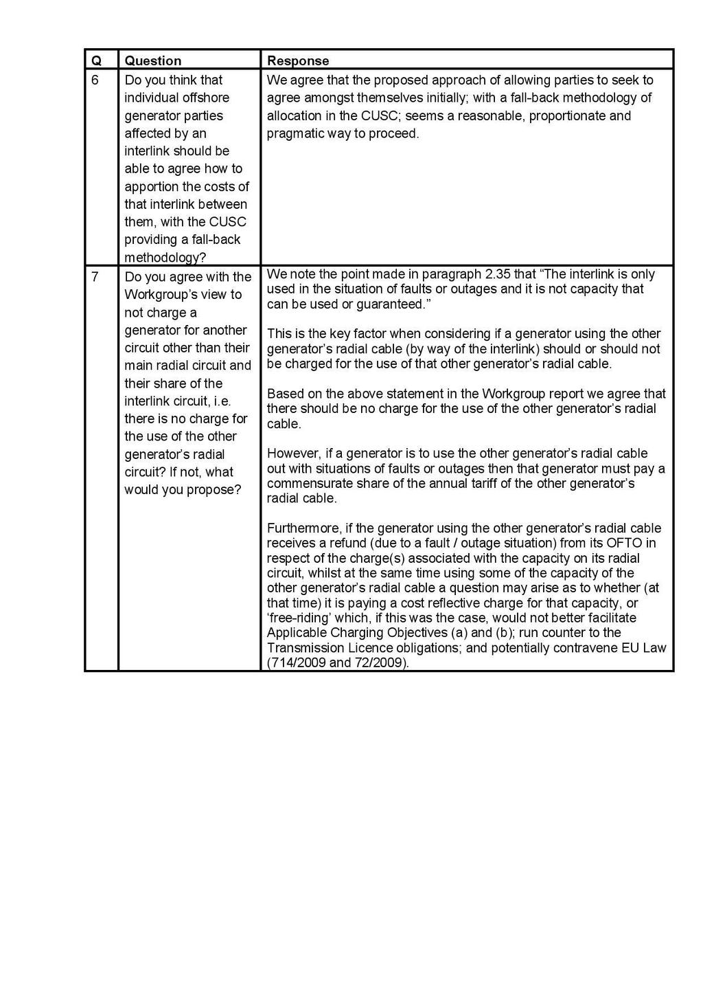
70 70 of 81

71 71 of 81
72 72 of 81
 allows Transmission Owners to recover the costs of building, owning and maintaining")
73 Annex 5 Guide to TNUoS Charging Methodology for Offshore Generation in GB This section is included at the request of Workgroup members, prepared by National Grid, to help the reader understand the background to the Offshore Charging Methodology in GB The Transmission Network Use of System Charges (TNUoS) allows Transmission Owners to recover the costs of building, owning and maintaining transmission assets; be they located onshore or offshore. The underlying rationale behind Transmission Network Use of System charges is that efficient economic signals are provider to Users when services are priced to reflect the cost of supplying them (CUSC ). For offshore generation, the TNUOS charges recover the cost of building, owning and maintaining transmission assets required to connect an offshore generator to the onshore transmission system. The TNUoS charge recovers revenue for the Offshore Transmission System Operators (OFTO) and for the onshore Transmission Owners (TO). Both OFTOs and Onshore TOs are required to hold an electricity transmission licence as defined in the Electricity Act The TNUoS Charging Methodology is defined in Section 14 of the Connection and Use of System Code (CUSC). The methodology applied to offshore generation is based on the methodology used for onshore generation; however, the specificities of the costs, design and regime for offshore generation is reflected in the charging methodology as detailed below. Design of offshore connections The design criteria for the GB Transmission Network are defined in the (GB) Security and Quality of Supply Standard (SQSS). The SQSS specifies the Offshore Standard Design as the specification that is to be used to connect an offshore generator to the National Electricity Transmission System. The criteria for offshore design are different to those for the onshore transmission network and allow a lower level of redundancy. This difference, seeks to partly offset the high costs of building and maintaining offshore circuits and substations. In general under the Offshore Standard Design, an offshore generator will be connected to the transmission network via a single radial circuit via an offshore and onshore OFTO substation. This general setup is illustrated in the following diagram: The capacity of the OFTO circuit and the ratings of any of the equipment in the substations (e.g. transformers, switchgear) are chosen to support the connected generation, whilst generally being of standard sizes available on the market to reduce the additional costs of bespoke equipment. This result in potentially larger capacity equipment, such as transformers, being installed that the TEC capacity of the generator being connected. In certain circumstances, the offshore generator will also be liable for an onshore circuit charge if the OFTO onshore substation is connected to the Main Integrated Transmission System (MITS) via a non-mits substation. If the connection to the MITS is via a distribution circuit, then a distribution charge will also be levied. 73 of 81
74 A particular feature of the offshore single-circuit radial design is that there is no redundancy provided to the generator in the event of a circuit or other fault. As this is a known factor, and consistent with the approved position in the SQSS, the circumstances when an offshore generator is liable for compensation, known as interruption payments in the CUSC, are different to onshore generators. Interruption Payments and Compensation As defined in Section 5 of the CUSC (Default, Deenergisation and Disconnection) a generator becomes eligible for an Interruption Payment in the event of a Relevant Interruption. Relevant Interruption are defined as an Interruption other an Allowed Interruption. One of the requirements for having a standard offshore design is the inclusion of Clause 10 in the Bilateral Connection Agreement (BCA) for the generator. Clause 10 provides that outages associated with a single radial circuit are considered Allowed Interruptions. This means that offshore generators are not eligible for Interruption Payments under the CUSC for circuit outages and/or restrictions associated with a single radial circuit design. An offshore generator may decide to pay more for their connection to have additional security (such as another circuit) included in their transmission connection design. Ultimately, Ofgem decides what elements of an offshore design are permitted, when assets are transferred and the allowable revenue is determined. Subject to approval, this additional security would be reflected in their circuit charge. In this situation, different criteria would apply in the BCA which may allow for interruption payments in the event of some outages, for example, in general configuration other than a single circuit (such as a double circuit) may mean a generator would be eligible for a CUSC Interruption Payment if that circuit were unavailable, but these would be agreed on a case-by-case basis based the individual scenario. Although offshore generators who have a Clause 10 BCA cannot claim a CUSC Interruption Payment associated with outages of their radial circuits, the licence for an OFTO includes an availability incentive requiring them to achieve a target availability for their circuit. OFTOs are incentivised to achieve these figures and are penalised for failing to achieve it. The precise formulation of the target is different for the different tender rounds of OFTOs but the overall principle remains the same. If an OFTOs fail to meet their target availability as specified in their licence, then their allowed revenue would be reduced, however, this will not directly affect the generators tariff due to the way in which offshore tariffs are set. Charging methodology for an offshore generator The TNUoS tariff for an offshore generator is composed of several parts: The offshore substation tariff related to the assets at the offshore substation, specific to the generator The offshore circuit tariff related to the cost of the OFTO circuit, specific to the generator The wider tariff associated with the use of the Main Interconnected Transmission System Depending on their type of connection, offshore generators may also pay for a local onshore circuit (if there is such a circuit prior to the MITS), and for connection via a distribution system. In common with the onshore charging methodology an offshore generator only pays onshore substation charges associated with the first substation they are connected to. The costs of the OFTO Onshore substation are socialised into the wider tariff element of TNUoS. 74 of 81
 in accordance with the charging methodology.")
75 OFTO Revenue The amount of money to be recovered through TNUoS for an OFTO in a given charging year is termed its revenue. National Grid pays this revenue to the OFTO and then seeks to recover it via TNUoS Charges from the User(s) in accordance with the charging methodology. To calculate the offshore substation tariff and the offshore local circuit tariff applicable to a generator, the OFTO revenue is first tagged to the specific radial circuit and offshore substation that it relates to. Any revenue not captured through these offshore substation and offshore local circuit tariffs is included in the wider tariff which socialises the remaining revenue. On page 77is a worked example for a fictional OFTO and generator. In this example there is a offshore generator connected via a single radial OFTO circuit. The generator has TEC of 400MW, and the single radial circuit has capacity of 420MW. The fictional OFTO has a revenue of 25M per annum. Local offshore circuit tariff The amount of revenue attributed to the offshore circuit tariff is the OFTO revenue multiplied by the ratio of the circuit capital cost to the total capital cost. In the worked example the capital cost of the circuit is 116M and the total capital cost is 303.5M; the proportion of the capital cost of the circuit (to the total capital cost) is therefore 38%. The total revenue is 25M, so the proportion of the revenue associated with the circuit is therefore, 38% x 25M = 9.55M. The local security factor (LSF) is a scaling factor included to represent the additional cost associated with the benefit of having redundancy in a design. If there is a single radial circuit (i.e. the standard offshore design), then the local security factor is 1. If there are multiple electrically connected circuits, then the local security factor is calculated as: LSF = Maximum Export Capacity of Circuits Generator TEC. The Local Security Factor is capped at 1.8; the same as the onshore security factor. The local offshore circuit tariff is calculated as: local offshore circuit tariff = local security factor OFTO Revenue Circuit Rating. In the worked example, as we have a single circuit, the LSF is 1. The local offshore circuit tariff = 1 x 9.55M / 420 MW = /kw. 75 of 81
CUSC Section 15 (CMP192) User Commitment Methodology
 User Commitment Methodology") CUSC Section 15 (CMP192) User Commitment Methodology Guidance and Implementation Document 1 May 2012 Version 1 1 1. Summary... 3 2. Purpose of the document...3 3. Background... 4 4. Attributable and Wider
CUSC Section 15 (CMP192) User Commitment Methodology Guidance and Implementation Document 1 May 2012 Version 1 1 1. Summary... 3 2. Purpose of the document...3 3. Background... 4 4. Attributable and Wider
P294 Addition of Offshore Transmission System and OTSUA to the definition of the Total System
 Stage 03: Assessment Report What stage is this document in the process? Addition of Offshore Transmission System and OTSUA to the definition of the Total System Amend the BSC definition of Total System
CMP303 - Improving local circuit charge cost-reflectivity
 CMP303 - Improving local circuit charge cost-reflectivity This modification seeks to make part of the TNUoS charge more cost-reflective through removal of additional costs from local circuit expansion
TNUoS Tariffs in 10 minutes March 2018
 TNUoS s in 10 minutes March 2018 An overview of TNUoS tariffs This information paper provides an overview of National Grid s Transmission Network Use of System (TNUoS) tariffs, applicable to transmission
CMP222 User Commitment for Non- Generation Users Volume 1
 Stage 06: Final CUSC Modification Report Connection and Use of System Code (CUSC) CMP222 User Commitment for Non- Generation Users Volume 1 This proposal seeks to introduce enduring User Commitment arrangements
Guidance and Implementation Document
 CUSC Section 15 (CMP192) User Commitment Methodology Guidance and Implementation Document February 2013 Version 0.1 1 1. Summary... 3 2. Purpose of the document... 3 3. Background... 4 4. Attributable
User Commitment for Generator Focused Anticipatory Investment (GFAI)
") All Industry Parties Patrick Hynes Electricity Charging & Capacity Development Manager patrick.hynes@nationalgrid.com Direct tel.: 01926 656319 22 nd May 2015 Dear Colleagues, User Commitment for Generator
All Industry Parties Patrick Hynes Electricity Charging & Capacity Development Manager patrick.hynes@nationalgrid.com Direct tel.: 01926 656319 22 nd May 2015 Dear Colleagues, User Commitment for Generator
Loss of Transmission Access Compensation Guidance Note for Customers
 Loss of Transmission Access Compensation Guidance Note for Customers This document has been produced to complement the Loss of Transmission Access Compensation Claim Form. Both the claim form and this
CA045 Arrangements for User Commitment
 Stage 02: Proposed System Operator Transmission Owner Code (STC) CA045 Arrangements for User Commitment What stage is this document at? 01 02 03 Initial Proposed Amendment Report This proposal seeks to
CUSC - SECTION 14 CHARGING METHODOLOGIES CONTENTS
 CUSC - SECTION 14 CHARGING METHODOLOGIES CONTENTS 14.1 Introduction Part I -The Statement of the Connection Charging Methodology 14.2 Principles 14.3 The Calculation of the Basic Annual Connection Charge
Five-Year Forecast Of TNUoS Tariffs For 2018/19 to 2022/23
 Five-Year Forecast Of TNUoS Tariffs For 2018/19 to 2022/23 November 2017 NGET: Forecast TNUoS tariffs for 2018/19 June 2017 1 Five-Year Forecast of TNUoS Tariffs for 2018/19 to 2022/23 This information
UK s Offshore Transmission Regime:
 UK s Offshore Transmission Regime: A case study for financing a low carbon future Stephanie McGregor Director Offshore Transmission June 2011 Today s presentation 1. Big picture 2. The OFTO 3. Making the
CMP223 Arrangements for Relevant Distributed Generators Under the Enduring Generation User Commitment
 Stage 04: Code Administrator Consultation Connection and Use of System Code (CUSC) CMP223 Arrangements for Relevant Distributed Generators Under the Enduring Generation User Commitment 01 02 03 04 05 What
Stage 01: Workgroup Report
 Stage 01: Workgroup Report National Electricity Transmission System Security and Quality of Supply Standards (NETS SQSS) GSR020: The Modification of Clause 7.8.1.1 to Allow Single Transformer Offshore
CONNECTION OF OFFSHORE WIND ONSHORE -- Some Food for Thought to Aid the Discussion at the Post-Conference Workshop
 Deeper Water Offshore Wind Conference by GIC CONNECTION OF OFFSHORE WIND ONSHORE -- Some Food for Thought to Aid the Discussion at the Post-Conference Workshop Dr Chuan Zhang The Crown Estate, UK London,
CMP223 Arrangements for
 Stage 02: 03: Workgroup Consultation Report Connection and and Use Use of of System Code (CUSC) CMP223 Arrangements for Relevant Distributed Generators Under the Enduring Generation User Commitment What
Connection and Use of System Charge Methodology Statement ("Condition 25 Statement")
") Connection and Use of System Charge Methodology Statement ("Condition 25 Statement") Revised Effective Date: 1 st January 2016 Approved by the Authority for Electricity Regulation, Oman Connection and
Connection and Use of System Charge Methodology Statement ("Condition 25 Statement") Revised Effective Date: 1 st January 2016 Approved by the Authority for Electricity Regulation, Oman Connection and
CMP282: The effect Negative Demand has on Zonal Locational Demand Tariffs. CUSC Modification Proposal Form
 CUSC Modification Proposal Form CMP282: The effect Negative has on Zonal Locational Tariffs At what stage is this document in the process? 01 02 Proposal Form Workgroup Consultation 03 Workgroup Report
TRANSMISSION CHARGING STATEMENT
 TRANSMISSION CHARGING STATEMENT 1 September 2016 1 September 2016 TABLE OF CONTENTS Page 1 Introduction... 1 2 General System Charges... 4 3 Site Specific Charges... 5 4 Connection Assets... 8 5 Least
TNUoS Forecasting Seminar. National Grid House, Warwick 23 November 2017
 TNUoS Forecasting Seminar National Grid House, Warwick 23 November 2017 0 Welcome Paul Wakeley Revenue Manager 1 Housekeeping 2 National Grid TNUoS Team Louise Schmitz Oversees the TNUoS and the CUSC Development
Transmission Charging Methodologies Forum
 Transmission Charging Methodologies Forum Place your chosen image here. The four corners must just cover the arrow tips. For covers, the three pictures should be the same size and in a straight line. Tuesday
CAP189 Standard Gas Insulated Switchgear (GIS) Ownership Boundaries
 Ownership Boundaries") Stage 05: Draft CUSC Connection and Use of System Code (CUSC) CAP189 Standard Gas Insulated Switchgear (GIS) Ownership Boundaries This proposal seeks to modify the CUSC such that a User requesting a connection
Stage 05: Draft CUSC Connection and Use of System Code (CUSC) CAP189 Standard Gas Insulated Switchgear (GIS) Ownership Boundaries This proposal seeks to modify the CUSC such that a User requesting a connection
DRAFT STCP 18-1 Issue 004 Connection and Modification Application
 STCP 18-1 Connection and Modification Application Draft Issue 004 - June 2014 DRAFT STCP 18-1 Issue 004 Connection and Modification Application STC Procedure Document Authorisation Party Name of Party
Transmission Charging Methodologies Forum
 Transmission Charging Methodologies Forum Place your chosen image here. The four corners must just cover the arrow tips. For covers, the three pictures should be the same size and in a straight line. 11
CMP239 Grandfathering Arrangements for the Small Generator Discount
 CMP239 Grandfathering Arrangements for the Small Generator Discount Place your chosen image here. The four corners must just cover the arrow tips. For covers, the three pictures should be the same size
CMP264/265 Implementation to TNUoS Tariffs. Paul Wakeley
 CMP264/265 Implementation to TNUoS Tariffs Paul Wakeley What are these Mods? CMP264 CMP265 Embedded Generation Triad Avoidance Standstill Gross charging of TNUoS for HH demand where embedded generation
STCP 16-1 Issue 005 Investment Planning
 STCP 16-1 Issue 005 Investment Planning STC Procedure Document Authorisation Company Name of Party Representative Signature Date National Grid Electricity Transmission plc SP Transmission plc Scottish
The South African Grid Code. Transmission Tariff Code. Version 9.0
 The South African Grid Code Transmission Tariff Code Version 9.0 This document is approved by the National Energy Regulator of South Africa (NERSA) Issued by: RSA Grid Code Secretariat Contact: Mr. Bernard
CUSC Modification Proposal Form CMP235
 CUSC Modification Proposal Form CMP235 Connection and Use of System Code (CUSC) Title of the CUSC Modification Proposal Introduction of a new Relevant Interruption type when a User has had to Emergency
CUSC Modification Proposal Form CMP259
 CUSC Modification Proposal Form CMP259 Connection and Use of System Code (CUSC) Title of the CUSC Modification Proposal Clarification of decrease in TEC as a Modification Submission Date 20 January 2016
A Scottish Hydro Electric Transmission plc project co-funded by the European Union under the European Energy Programme for Recovery (EEPR)
") Offshore HVDC Hub project (2009 2012) A Scottish Hydro Electric Transmission plc project co-funded by the European Union under the European Energy Programme for Recovery (EEPR) Scottish Hydro Electric
Offshore HVDC Hub project (2009 2012) A Scottish Hydro Electric Transmission plc project co-funded by the European Union under the European Energy Programme for Recovery (EEPR) Scottish Hydro Electric
CUSC - SECTION 3 USE OF SYSTEM CONTENTS
 CUSC - SECTION 3 USE OF SYSTEM CONTENTS 3.1 Introduction PART IA - GENERAL - GENERATION 3.2 Rights to Use the National Electricity Transmission System 3.3 Other Site Specific Technical Conditions for Embedded
Further information on mid-year tariff changes following the September 2010 Customer Seminars
 Further information on mid-year tariff changes following the September 2010 Customer Seminars National Grid received a number of questions at the Customer Seminars on National Grid s proposal to update
CUSC Amendment Proposal Form CAP: 161
 CUSC Amendment Proposal Form CAP: 161 Title of Amendment Proposal: Transmission Access System Operator Release of Short-term Entry Rights Description of the Proposed Amendment (mandatory by proposer):
CMP291. Garth Graham for SSE Generation Ltd. CUSC Panel 23 rd February 2018
 CMP291 The open, transparent, non discriminatory and timely publication the harmonised rules for grid connection (in accordance with the RfG, DCC and HVDC) and the harmonised rules on system operation
STCP19-5 Issue 002 Offshore Transmission System Compliance Process & Testing
 STCP19-5 Issue 002 Offshore Transmission System Compliance Process & Testing STC Procedure Document Authorisation Company National Grid Electricity Transmission plc Name of Party Representative Signature
CMP288: Explicit charging arrangements for customer delays and backfeeds.
 CUSC Modification Proposal Form CMP288: Explicit charging arrangements for customer delays and backfeeds. At what stage is this document in the process? 01 02 Proposal Form Workgroup Consultation 03 Workgroup
Transmission Charging Methodologies Forum. 11:00am 3:00pm National Grid House, Warwick
 Meeting report Meeting name Date of meeting 14 th January 2015 Time Location Transmission Charging Methodologies Forum 11:00am 3:00pm National Grid House, Warwick Attendees Name Initials Company Patrick
UNC 0686 (Urgent): Removal of the NTS Optional Commodity Rate with adequate notice. UNC Modification
: Removal of the NTS Optional Commodity Rate with adequate notice. UNC Modification") UNC Modification At what stage is this document in the process? UNC 0686 (Urgent): Removal of the NTS Optional Commodity Rate with adequate notice Purpose of Modification: Removal of the NTS Optional Commodity
UNC Modification At what stage is this document in the process? UNC 0686 (Urgent): Removal of the NTS Optional Commodity Rate with adequate notice Purpose of Modification: Removal of the NTS Optional Commodity
Distributed Generation Connection Standard ST B Planning Engineer. Network Planning Manager. General Manager Network
 Effective Date 1 May 2018 Issue Number 1.1 Page Number Page 1 of 26 Document Title Distributed Generation Connection Standard Document Number ST B1.1-001 Document Author Planning Engineer Document Reviewer
TRANSGRID PRICING METHODOLOGY 2015/ /18. Contents
 Pricing Methodology TRANSGRID PRICING METHODOLOGY 2015/16 2017/18 Contents Pricing Methodology 1 Introduction 3 2 Duration 3 3 Which services are subject to this pricing methodology? 4 4 Overview of the
Contents Introduction Chapter 1 - Security Policy... 6
 Policy statement Contents Introduction... 5 PURPOSE... 5 SYSTEM OPERATOR POLICIES TO ACHIEVE THE PPOS and dispatch objective... 5 Avoid Cascade Failure... 5 Frequency... 6 Other Standards... 6 Restoration...
Wairakei Ring Investment Proposal. Project Reference: CTNI_TRAN-DEV-01. Attachment A GIT Results
 Wairakei Ring Investment Proposal Project Reference: CTNI_TRAN-DEV-01 Attachment A GIT Results December 2008 Document Revision Control Document Number/Version 001/Rev A Description Wairakei Ring Investment
Transmission Charging Methodologies Forum. National Grid House, Warwick
 Meeting report Meeting name Date of meeting 9 th September 2015 Time 11:00 14:00 Location Transmission Charging Methodologies Forum National Grid House, Warwick Attendees Name Initials Company Paul Wakeley
Project Assessment Conclusions Report
 Powerlink Queensland Project Assessment Conclusions Report 27 August 2018 Addressing the secondary systems condition Disclaimer While care was taken in preparation of the information in this document,
Final TNUoS Tariffs for 2018/19
 Final TNUoS Tariffs for 2018/19 January 2018 NGET: Forecast TNUoS Tariffs for 2018/19 June 2017 1 Final TNUoS tariffs for 2018/19 This information paper provides National Grid s Final Transmission Network
SP Transmission successfully fast-tracked
 2 RIIO-T1 Transmission Price Control January 2012 SP Transmission successfully fast-tracked SP Transmission is pleased to announce that it has reached agreement with the Government energy regulator Ofgem
TRANSMISe,,/ Blue Transmission Walney 2 Limited. Regulatory accounts 2017/18
 TRANSMISe,,/ Blue Transmission Walney 2 Limited Regulatory accounts 2017/18 Contents Page 2 A description of these regulatory accounts 3 Strategic Report 23 Directors Report 25 Corporate governance statement
Forecast TNUoS Tariffs for 2019/20
 Forecast TNUoS Tariffs for 2019/20 April 2018 NGET: Forecast TNUoS Tariffs for 2019/20 June 2017 1 Forecast TNUoS Tariffs for 2019/20 This information paper provides National Grid s April Forecast Transmission
COMPARISION OF OFFSHORE REQUIREMENTS
 Key to Table COMPARISION OF OFFSHORE REQUIREMENTS (Comparison based on GB Grid Code Issue 4 Revision 13 only and ENSTO - E RFG Internal Version dated 26 June 2012) (Note Does not include other Industry
Entry Capacity Substitution Methodology Statement
 Issue Revision 7.0 Approved Entry Substitution Methodology Statement Effective from 1 st November 2015 Page 1 of 30 ENTRY CAPACITY SUBSTITUTION METHODOLOGY STATEMENT Document Revision History Version/
WoDS Transmission plc
 Regulatory accounts 2016/17 WoDS Transmission plc TRANSMISS[bN WoDS J Contents Page 2 A description of these regulatory accounts 3 Strategic report 25 Directors report 27 Corporate governance statement
CHARGES APPLICABLE 9 TH OCTOBER 2008
 METHODOLOGY STATEMENT DETAILING THE BASIS OF CHARGES FOR CONNECTION TO SP MANWEB PLC S ELECTRICITY DISTRIBUTION SYSTEM CHARGES APPLICABLE 9 TH OCTOBER 2008 NOTE THIS STATEMENT IS SUBJECT TO THE APPROVAL
QUALITY CONTROL Prepared: D. Vree Reviewed: M. Müller Approved: F. Wester BACKGROUND MATERIAL...
 POSITION PAPER STAKE HOLDER CONSULTATION PROCESS OFFSHORE GRID NL Type: Position paper Work stream Technical Topic: T.6 Protection Filename ONL 15-080-T6_Protection_PP_v1 Version 1 - release for Expert
Direct Dial: August Our Ref: MP No P125
 Direct Dial: 020 7901 7412 The National Grid Company, BSC Signatories and Other Interested Parties 08 August 2003 Our Ref: MP No P125 Dear Colleague Modification to the Balancing and Settlement Code (
Name Initials Position
 Minutes Meeting name CUSC Modifications Panel Meeting number 209 Date of meeting 30 June 2017 Location National Grid House, Warwick Attendees Name Initials Position Mike Toms MT Panel Chair Caroline Wright
Gas Networks Ireland Transmission Tariffs and Tariff Information 2018/19
 An Coimisiún um Rialáil Fóntas Commission for Regulation of Utilities Gas Networks Ireland Transmission Tariffs and Tariff Information 2018/19 Information Paper Information Paper Reference: CRU/18/179
George Moran, British Gas 28th August 2015
 CMP 251: Removing the error margin in the cap on total TNUoS recovered by generation and introducing a new charging element to TNUoS to ensure compliance with European Commission Regulation 838/2010 George
National Grid response to the open letter on BELLA participation in the Balancing Mechanism
 National Grid House Warwick Technology Park Gallows Hill, Warwick CV34 6DA Electricity Industry Colleagues and Interested Parties Ian Pashley Electricity Codes Manager Transmission Ian.pashley@nationalgrid.com
Docket No. QX In the Matter of Offshore Wind Renewable Energy Certificate (OREC) Funding Mechanism
 Funding Mechanism") May 18, 2018 Aida Camacho-Welch Secretary of the Board Board of Public Utilities 44 South Clinton Avenue, 3rd Floor, Suite 314 Post Office Box 350 Trenton, New Jersey 08625-0350 Re: Docket No. QX18040466
May 18, 2018 Aida Camacho-Welch Secretary of the Board Board of Public Utilities 44 South Clinton Avenue, 3rd Floor, Suite 314 Post Office Box 350 Trenton, New Jersey 08625-0350 Re: Docket No. QX18040466
APPLICATION PROVISIONS
 Application Provisions 1 APPLICATION PROVISIONS Regional Network Tariffs 2018-01-01 Vattenfall Eldistribution AB Application Provisions 2 PRICING OF NETWORK SERVICES ON VATTENFALL'S REGIONAL NETWORKS Table
Twelfth Revised Sheet No FLORIDA POWER & LIGHT COMPANY Cancels Eleventh Revised Sheet No INDEX OF CONTRACTS AND AGREEMENTS
 Twelfth Revised Sheet No. 10.001 FLORIDA POWER & LIGHT COMPANY Cancels Eleventh Revised Sheet No. 10.001 INDEX OF CONTRACTS AND AGREEMENTS Sheet No. Contract Provisions - Various 10.010 Distribution Substation
Addressing under-allocation of flows from BBL arising from misalignment of reference conditions
 Stage 01: Modification 0560 Urgent: Addressing under-allocation of flows from BBL arising from misalignment of reference conditions At what stage is this document in the process? 01 Modification 02 03
stated. This Ruling applies is the issue Manager. b) of Asteron A Life PO P Box 2198 Wellington W 6140 New N Zealand Telephone: T
 of Asteron A Life PO P Box 2198 Wellington W 6140 New N Zealand Telephone: T") Office O of the Chief Tax Counsel Te T Tari o te Rōia Tāke Matua Asteron A Life 555 Featherstonn Street PO P Box 2198 Wellington W 6140 New N Zealand Telephone: T 044 890-1500 Facsimile F Numbers: Chief
Office O of the Chief Tax Counsel Te T Tari o te Rōia Tāke Matua Asteron A Life 555 Featherstonn Street PO P Box 2198 Wellington W 6140 New N Zealand Telephone: T 044 890-1500 Facsimile F Numbers: Chief
4.2 Definitions In this Clause 4 and Schedule E the following terms shall have the meanings ascribed to them below:-
 4. BLACK START CAPABILITY [Note: this clause will need substantial amendment to reflect the circumstances of any individual case, for example the type of Black Start Plant, use of distillate fuel, whether
Invitation to Tender
 Invitation to Tender November 2016 BRIEF FOR CONSULTANT TO CARRY OUT A NETWORK ANALYSIS OF THE WESTERN ISLES GRID, A REVIEW OF BUDGET ESTIMATES RECEIVED AND A STUDY ON FUTURE INNOVATIVE CONNECTION OPTIONS
The current ETSO ITC Model and possible development
 The current ETSO ITC Model and possible development 1. Summary The present model for inter-tso compensation for transit (ITC) was introduced in 2002 and has been modified step-by-step from year to year.
SCHEDULE 85 COGENERATION AND SMALL POWER PRODUCTION STANDARD CONTRACT RATES
 IDAHO POWER COMPANY FOURTH REVISED SHEET NO. 85-1 THIRD REVISED SHEET NO. 85-1 AVAILABILITY Service under this schedule is available for power delivered to the Company's control area within the State of
Station Power Standby Service Schedule Designation R3 Standard Contract Rider No. 3
 Station Power Standby Service Schedule Designation R3 Standard Contract Rider No. 3 DE 963-1826 2/17 THIS RIDER, dated 20, is attached to and becomes a part of an electric service agreement dated 20, between,
PAUL CHERNICK ELLEN HAWES
 STATE OF NEW HAMPSHIRE BEFORE THE PUBLIC UTILITIES COMMISSION Development of New Alternative Net Metering ) Tariffs and/or Other Regulatory Mechanisms ) Docket No. DE 1- and Tariffs for Customer-Generators
TRIP OF VALES POINT 330 KV MAIN BUSBAR ON 27 JULY 2017 REVIEWABLE OPERATING INCIDENT REPORT UNDER THE NATIONAL ELECTRICITY RULES
 TRIP OF VALES POINT 330 KV MAIN BUSBAR ON 27 JULY 2017 REVIEWABLE OPERATING INCIDENT REPORT UNDER THE NATIONAL ELECTRICITY RULES Published: 26 September 2017 INCIDENT CLASSIFICATIONS Classification Detail
Variation Request. Modification 0510 Reform of Gas Allocation Regime at GB Interconnection Points
 Variation Request Modification 0510 Reform of Gas Allocation Regime at GB Interconnection Points Date: 3 rd July 2015 The Proposer, National Grid NTS, requests a variation to this Modification, pursuant
Final Annual Load Factors for 2018/19 TNUoS Tariffs
 Final Annual Load Factors for 2018/19 TNUoS Tariffs November 2017 reissued January 2018 NGET: Final s for 2018/19 TNUoS Tariffs October 2017 1 Final Annual Load Factors for 2018/19 TNUoS Tariffs This information
Inclusion and Amendment of Entry Incremental Capacity Release NPV test in UNC
 UNC Modification At what stage is this document in the process? UNC 0667: Inclusion and Amendment of Entry Incremental Capacity Release NPV test in UNC Purpose of Modification: This Modification seeks
The Entry Capacity Substitution Methodology Statement
 Issue 5.26.1 Revision Informal Consultation Draft The Entry Substitution Methodology Statement Effective from 2 nd February1 st September 2015 Page 1 of 31 ENTRY CAPACITY SUBSTITUTION METHODOLOGY STATEMENT
California Independent System Operator Corporation Fifth Replacement Electronic Tariff
 Table of Contents Appendix F Rate Schedules... 2 Schedule 1... 2 Grid Management Charge... 2 Part A Monthly Calculation of Grid Management Charge (GMC)... 2 Part B Quarterly Adjustment, If Required...
ACER Consultation Template. Tariff NC Article 26(5)
") ACER Consultation Template Tariff NC 26(5) The following document constitutes support material for the online template created by the Agency for the Coordination of Energy Regulators ( the Agency) for
ACER Consultation Template Tariff NC 26(5) The following document constitutes support material for the online template created by the Agency for the Coordination of Energy Regulators ( the Agency) for
Contributions Policy
 ELECTRICITY NETWORKS CORPORATION ( WESTERN POWER ) ABN 18 540 492 861 {Outline: This contributions policy is included in Western Power s access arrangement in accordance with section 5.1(h) of the Code.}
ERGEG Public Consultation on Guidelines on Transmission Tarification 1. - Evaluation of the Comments Received
 ERGEG Public Consultation on Guidelines on Transmission Tarification 1 - Evaluation of the Comments Received - 18-07-2005 INTRODUCTION This document contains the evaluation by ERGEG of the comments received
SOLAR PV INSTALLATION AT USC BASEBALL STADIUM
 AMENDMENT NO. 7 TO SOLICITATION TO: ALL VENDORS FROM: Charles Johnson, Procurement Manager SUBJECT: SOLICITATION NUMBER: USC-RFP-1761-CJ SOLAR PV INSTALLATION AT USC BASEBALL STADIUM DATE: June 30, 2010
Handbook for Optimised. Deprival Valuation of System Fixed Assets of. Electricity Lines Businesses
 Handbook for Optimised Deprival Valuation of System Fixed Assets of Electricity Lines Businesses REVISED DRAFT FOR CONSULTATION 9 July 2004 Adjusted for Transpower Comments Deleted: 15 Deleted: 14 Inserted:
System Operating Policies on Compensation between Elia and Nemo Link
 System Operating Policies on Compensation between Elia and Nemo Link 1 WHEREAS Elia and Nemo Link have entered into the Joint Operation Agreement ( JOA ) on the 25 th of February 2015 for the purpose of
Regional Network Tariffs applicable commenting
 Regional Network Tariffs applicable commenting 2019-01-01 Table of contents 1. Connection... 3 2. Pricing of network services on Vattenfall s regional network... 4 3. Normal tariff for withdrawals of electricity
Section T: Settlement and Trading Charges. how Trading Charges for each Trading Party and National Grid are determined;
 BSC Simple Guide Section T: Settlement and Trading Charges Section T sets out: (a) (b) (c) how Trading Charges for each Trading Party and National Grid are determined; the data required in order to calculate
ESKOM S CONNECTION CHARGES METHODOLOGY
 ESKOM S CONNECTION CHARGES METHODOLOGY 13 November 2007 This document may be updated from time to time. Please refer to www.eskom.co.za/tariffs for the latest version. Eskom s Connection Charges Methodology
Offshore transmission investments How to regulate these investments? Who should act?
 Offshore transmission investments How to regulate these investments? Who should act? North Seas Countries Offshore Grid Initiative (NSCOGI) Copenhagen, 18-19 April 2012 Leonardo Meeus (Florence School
RECITALS. Now, Therefore, in consideration of the mutual covenants and agreements herein set forth, the Parties do hereby agree as follows:
 LEE COUNTY ELECTRIC COOPERATIVE STANDARD INTERCONNECTION AGREEMENT FOR CUSTOMER-OWNED RENEWABLE GENERATION SYSTEMS GREATER THAN 100 KW AND LESS THAN OR EQUAL TO 1 MW TIER 3 This Interconnection Agreement
CASA-1000 Project List of FAQs
 1. What is the objective of the project? CASA-1000 Project List of FAQs The objective of the CASA-1000 project is to provide for the export of the available summer electricity surpluses from Tajikistan
Interconnector (UK) Limited. Charging Statement related to the IUK Access Agreement and IUK Access Code Issue 15 Applicable from 01 January 2019
 Limited. Charging Statement related to the IUK Access Agreement and IUK Access Code Issue 15 Applicable from 01 January 2019") Interconnector (UK) Limited Charging Statement related to the IUK Access Agreement and IUK Access Code Issue 15 Applicable from 01 January 2019 Issue 15 01 January 2019 1. Introduction... 1 2. Reserve
Interconnector (UK) Limited Charging Statement related to the IUK Access Agreement and IUK Access Code Issue 15 Applicable from 01 January 2019 Issue 15 01 January 2019 1. Introduction... 1 2. Reserve
Interconnector (UK) Limited. Charging Statement related to the IUK Access Agreement and IUK Access Code Issue 14 Applicable from 22 November 2018
 Limited. Charging Statement related to the IUK Access Agreement and IUK Access Code Issue 14 Applicable from 22 November 2018") Interconnector (UK) Limited Charging Statement related to the IUK Access Agreement and IUK Access Code Issue 14 Applicable from 22 November 2018 Issue 14 22 November 2018 1. Introduction... 1 2. Reserve
Interconnector (UK) Limited Charging Statement related to the IUK Access Agreement and IUK Access Code Issue 14 Applicable from 22 November 2018 Issue 14 22 November 2018 1. Introduction... 1 2. Reserve
SERVICE CLASSIFICATION NO. 14-RA STANDBY SERVICE
 Fourth Revised Leaf No. 135 Consolidated Edison Company Superseding Second Revised Leaf No. 135 (Third Revised Leaf No. 135 Canceled) Applicable to Use of Service for SERVICE CLASSIFICATION NO. 14-RA The
The North Seas Countries Offshore Grid Initiative
 The North Seas Countries Offshore Grid Initiative Deliverable 1 - final report This report identifies areas where the incompatibility of national market and regulatory regimes acts as a barrier to coordinated
UNIQUE ATTRIBUTES OF RENEWABLE POWER PURCHASE AGREEMENTS
 11.11.2009 UNIQUE ATTRIBUTES OF RENEWABLE POWER PURCHASE AGREEMENTS Power Purchase Agreements ( PPA ) are highly negotiated long term agreements through which power producers (often referred to as sellers)
Decision on Electricity Network Connection Policy
 Decision on Electricity Network Connection Policy DOCUMENT TYPE: REFERENCE: DATE PUBLISHED: QUERIES TO: Decision Paper CER/09/138 25 August 2009 John Orme (distribution@cer.ie) The Commission for Energy
ASSET RISK MANAGEMENT Asset Health Framework
 ASSET RISK MANAGEMENT Asset Health Framework 15 C O P Y R I G H T 2013 T R A N S P O W E R N E W Z E A L A N D L I M I T E D. A L L R I G H T S R E S E R V E D Preface This document has been prepared to
CAP189 Standard Gas Insulated Switchgear (GIS) Ownership Boundaries
 Ownership Boundaries") Stage 03: Workgroup Report Connection and Use of System Code (CUSC) CAP189 Standard Gas Insulated Switchgear (GIS) Ownership Boundaries What stage is this document at? 01 02 03 04 05 Initial Written Assessment
Stage 03: Workgroup Report Connection and Use of System Code (CUSC) CAP189 Standard Gas Insulated Switchgear (GIS) Ownership Boundaries What stage is this document at? 01 02 03 04 05 Initial Written Assessment
No. 19. Offshore Wind Energy in Europe Fresh Wind for Insurers, Too? A Berkshire Hathaway Company. Topics No. 19
 No. 19 Topics No. 19 Offshore Wind Energy in Europe Fresh Wind for Insurers, Too? A Berkshire Hathaway Company 10 Offshore Wind Energy in Europe Fresh Wind for Insurers, Too? Oliver Stein Oliver Stein
EU Capacity Regulations Capacity Allocation Mechanisms with Congestion Management Procedures
 Stage 02: Workgroup Report At what stage is this document in the process? : EU Capacity Regulations Capacity Allocation Mechanisms with Congestion Management Procedures This modification seeks to facilitate
The Entry Capacity Substitution Methodology Statement
 Issue 6.06.2 Revision ApprovedCons ultation Draft The Entry Substitution Methodology Statement Effective from 27 th February1 st November 2015 Page 1 of 32 The Entry Substitution Methodology Statement
Information Paper. Financial Capital Maintenance and Price Smoothing
 Information Paper Financial Capital Maintenance and Price Smoothing February 2014 The QCA wishes to acknowledge the contribution of the following staff to this report: Ralph Donnet, John Fallon and Kian