Case Material: Molded Plastic. UL Flammability Classification Low Reverse Leakage Current
|
|
|
- Barnaby Matthews
- 5 years ago
- Views:
Transcription

1 Pb 4A GLASS PASSIVATED BRIDGE RECTIFIER Features Mechanical Data Glass Passivated Die Construction Case: Rating to 1,000V PRV Case Material: Molded Plastic. UL Flammability Classification Low Reverse Leakage Current Rating 94V-0 Surge Overload Rating to 150A Peak Moisture Sensitivity: Level 1 per J-STD-020 Ideal for Printed Circuit Board Applications Terminals: Matte Tin Finish. Solderable per MIL-STD 202, Method Lead-Free Finish; RoHS Compliant (Notes 1 & 2) 208 Polarity: Marked on Body See Marking Information Below Marking: Date Code and Type Number Weight: 2.52 grams (Approximate) Ordering Information (Note 3) Part Number Qualification Case Packaging Commercial 20/Tube Notes: 1. EU Directive 2002/95/EC (RoHS) & 2011/65/EU (RoHS 2) compliant. All applicable RoHS exemptions applied. 2. See for more information about Diodes Incorporated s definitions of Halogen- and Antimony-free, "Green" and Lead-free. 3. For packaging details, go to our website at Marking Information = Product Type Marking Code = Manufacturers Code Marking YWW = Date Code Marking Y = Last Digit of Year (ex: 7 = 2017) WW = Week Code (01 53) 1 of 5
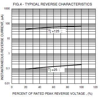
2 Maximum Ratings and Electrical Characteristics A = +25 C, unless otherwise specified.) Single phase, half wave, 60Hz, resistive or inductive load. For capacitive load, derate current by 20%. Characteristic Symbol Value Unit Peak Repetitive Reverse Voltage Working Peak Reverse Voltage DC Blocking Voltage V RRM V RWM V R 1,000 V RMS Reverse Voltage V R(RMS) 700 V With Heatsink 4.0 Average Forward Rectified Current (Note 4) I Without Heatsink (AV) A 2.4 Non-Repetitive Peak Forward Surge Current I 8.3ms Single Half Sine-Wave Superimposed on Rated Load FSM 150 A Forward Voltage (Per I F = 2.0A V FM 1.0 = +25 C 5 Peak Reverse Current at Rated DC Blocking Voltage C R 500 µa I 2 t Rating for Fusing (Note 5) I 2 t 93 A 2 s Typical Total Capacitance per Element (Note 6) C T 35 pf Typical Thermal Resistance Junction to Case (Note 4) R θjc 4.2 C/W Typical Thermal Resistance Junction to Lead R θjl 4.0 C/W Typical Thermal Resistance Junction to Ambient (Note 4) R θja 10 C/W Operating and Storage Temperature Range T J, T STG -55 to +150 C Notes: 4. Unit mounted on 50x50x1.6mm Cu plate heatsink. 5. Non-repetitive, for t > 3.0ms and < 8.3ms. 6. Measured at 1.0MHz and applied reverse voltage of 4.0V DC. 2 of 5

3 3 of 5
4 Package Outline Dimensions Please see for the latest version. h D a1 A A2 L1 b2 E L a Dim Min Max Typ A A b b c D E e h L L a a All Dimensions in mm b e c 4 of 5
5 IMPORTANT NOTICE DIODES INCORPORATED MAKES NO WARRANTY OF ANY KIND, EXPRESS OR IMPLIED, WITH REGARDS TO THIS DOCUMENT, INCLUDING, BUT NOT LIMITED TO, THE IMPLIED WARRANTIES OF MERCHANTABILITY AND FITNESS FOR A PARTICULAR PURPOSE (AND THEIR EQUIVALENTS UNDER THE LAWS OF ANY JURISDICTION). Diodes Incorporated and its subsidiaries reserve the right to make modifications, enhancements, improvements, corrections or other changes without further notice to this document and any product described herein. Diodes Incorporated does not assume any liability arising out of the application or use of this document or any product described herein; neither does Diodes Incorporated convey any license under its patent or trademark rights, nor the rights of others. Any Customer or user of this document or products described herein in such applications shall assume all risks of such use and will agree to hold Diodes Incorporated and all the companies whose products are represented on Diodes Incorporated website, harmless against all damages. Diodes Incorporated does not warrant or accept any liability whatsoever in respect of any products purchased through unauthorized sales channel. Should Customers purchase or use Diodes Incorporated products for any unintended or unauthorized application, Customers shall indemnify and hold Diodes Incorporated and its representatives harmless against all claims, damages, expenses, and attorney fees arising out of, directly or indirectly, any claim of personal injury or death associated with such unintended or unauthorized application. Products described herein may be covered by one or more United States, international or foreign patents pending. Product names and markings noted herein may also be covered by one or more United States, international or foreign trademarks. This document is written in English but may be translated into multiple languages for reference. Only the English version of this document is the final and determinative format released by Diodes Incorporated. LIFE SUPPORT Diodes Incorporated products are specifically not authorized for use as critical components in life support devices or systems without the express written approval of the Chief Executive Officer of Diodes Incorporated. As used herein: A. Life support devices or systems are devices or systems which: 1. are intended to implant into the body, or 2. support or sustain life and whose failure to perform when properly used in accordance with instructions for use provided in the labeling can be reasonably expected to result in significant injury to the user. B. A critical component is any component in a life support device or system whose failure to perform can be reasonably expected to cause the failure of the life support device or to affect its safety or effectiveness. Customers represent that they have all necessary expertise in the safety and regulatory ramifications of their life support devices or systems, and acknowledge and agree that they are solely responsible for all legal, regulatory and safety-related requirements concerning their products and any use of Diodes Incorporated products in such safety-critical, life support devices or systems, notwithstanding any devices- or systems-related information or support that may be provided by Diodes Incorporated. Further, Customers must fully indemnify Diodes Incorporated and its representatives against any damages arising out of the use of Diodes Incorporated products in such safety-critical, life support devices or systems. Copyright 2017, Diodes Incorporated 5 of 5
ZXBM1017 OBSOLETE PART DISCONTINUED PART OBSOLETE - USE ZXBM1021 VARIABLE SPEED SINGLE- PHASE BLDC MOTOR CONTROLLER ZXBM of 10
 VARIABLE SPEED SINGLE- PHASE BLDC MOTOR CONTROLLER 1 of 10 2 of 10 3 of 10 4 of 10 5 of 10 6 of 10 7 of 10 8 of 10 9 of 10 IMPORTANT NOTICE DIODES INCORPORATED MAKES NO WARRANTY OF ANY KIND, EXPRESS OR
OBSOLETE. Features. Mechanical Data PNP PRE-BIASED SMALL SIGNAL SURFACE MOUNT TRANSISTOR
 PNP PRE-BIASED SMALL SIGNAL SURFAE MOUNT TRANSISTOR Obsolete Part Number Alternative Part Number DDTA4EA DDTA5EA DDTA3EA DDTA4EA DDTA43EA DDTA44EA Features Epitaxial Planar Die onstruction omplementary
Is Now Part of To learn more about ON Semiconductor, please visit our website at
 Is Now Part of To learn more about ON Semiconductor, please visit our website at ON Semiconductor and the ON Semiconductor logo are trademarks of Semiconductor Components Industries, LLC dba ON Semiconductor
FFH60UP60S, FFH60UP60S3. 60 A, 600 V Ultrafast Rectifier
 FFH60UP60S, FFH60UP60S3 60 A, 600 V Ultrafast Rectifier Description The FFH60UP60S, FFH60UP60S3 is an ultrafast diode with low forward voltage drop and rugged UIS capability. This device is intended for
FS8G - FS8M. 8 A Standard Recovery Surface Mount Rectifiers
 8G - 8M 8 A tandard Recovery urface Mount Rectifiers Description The 8G to 8M series offers breakthrough size and performance. It sinks 8 A DC forward current and provides up to 20 A surge current capability
Top View BAS70WQ BAS70W-04Q BAS70W-05Q BAS70W-06Q
 SUC MOU SCHOKY BI DIOD Product Summary V M (V) I O (m) V (MX) @ 1m (V) I (MX) @ V = 50V (μ) 70 70 0.41 0.1 pplications SMPS DC-DC Converter reewheeling Diodes everse Polarity Protection Blocking Diodes
V RM = 600 V, I F(AV) = 1.0 A General-Purpose Rectifier Diode. Description. Package. Features. Applications
 = 1.0 A General-Purpose Rectifier Diode. Description. Package. Features. Applications") V RM = 600 V, I F(AV) = 1.0 A General-Purpose Rectifier Diode Data Sheet Description The is a 600 V, 1.0 A general-purpose rectifier diode with low loss characteristics. This rectifier diode is for a commercial
V RM = 600 V, I F(AV) = 1.0 A General-Purpose Rectifier Diode Data Sheet Description The is a 600 V, 1.0 A general-purpose rectifier diode with low loss characteristics. This rectifier diode is for a commercial
SYMBOL TYPE NUMBER VALUE UNIT. Power dissipation at Tamb = 60 ºC 1.5 W. Non repetitive peak zener dissipation (t = 10ms) 40 W
 40 W") DO-204AL (DO-41) Voltage Power Dissipation 10 to 200 V 1.5 W Maximum Ratings and Electrical Characteristics at 25 C FEATURE Glass passivated chip junction Hiperectifier structure for high reliability Cavity-free
DO-204AL (DO-41) Voltage Power Dissipation 10 to 200 V 1.5 W Maximum Ratings and Electrical Characteristics at 25 C FEATURE Glass passivated chip junction Hiperectifier structure for high reliability Cavity-free
V RSM = 400 V, I F(AV) = 2.0 A General-Purpose Rectifier Diode. Description. Package. Features. Applications (1) (2) (1) Cathode (2) Anode
 = 2.0 A General-Purpose Rectifier Diode. Description. Package. Features. Applications (1) (2) (1) Cathode (2) Anode") V RSM = 400 V, I F(AV) = A General-Purpose Rectifier Diode Data Sheet Description The is a 400 V, A general-purpose rectifier diode with low loss characteristics. This rectifier diode is for a commercial
V RSM = 400 V, I F(AV) = A General-Purpose Rectifier Diode Data Sheet Description The is a 400 V, A general-purpose rectifier diode with low loss characteristics. This rectifier diode is for a commercial
BAS70-00-V to BAS70-06-V
 Small Signal Schottky Diodes, Single & Dual Features These diodes feature very low turn-on voltage and fast switching These devices are protected by a PN junction guard ring against excessive voltage,
V RM = 600 V, I F(AV) = 0.5 A, t rr = 100 ns Fast Recovery Diode. Description. Package. Features. Applications
 = 0.5 A, t rr = 100 ns Fast Recovery Diode. Description. Package. Features. Applications") V RM = 600 V, I F(AV) = 0.5 A, t rr = 100 ns Fast Recovery Diode Data Sheet Description The is a fast recovery diode of 600 V / 0.5 A. The maximum t rr of 100 ns is realized by optimizing a life-time control.
V RM = 600 V, I F(AV) = 0.5 A, t rr = 100 ns Fast Recovery Diode Data Sheet Description The is a fast recovery diode of 600 V / 0.5 A. The maximum t rr of 100 ns is realized by optimizing a life-time control.
Is Now Part of To learn more about ON Semiconductor, please visit our website at
 Is Now Part of To learn more about ON emiconductor, please visit our website at www.onsemi.com ON emiconductor and the ON emiconductor logo are trademarks of emiconductor Components Industries, LLC dba
Is Now Part of. To learn more about ON Semiconductor, please visit our website at
 Is Now Part of To learn more about ON emiconductor, please visit our website at www.onsemi.com Please note: As part of the airchild emiconductor integration, some of the airchild orderable part numbers
V RSM = 30 V, I F(AV) = 2.0 A Schottky Diode. Description. Package. Features. Applications (1) (2) (1) Cathode (2) Anode
 = 2.0 A Schottky Diode. Description. Package. Features. Applications (1) (2) (1) Cathode (2) Anode") V RSM = 30 V, I F(AV) = A Schottky Diode Data Sheet Description The is a 30 V, A Schottky diode with allowing improvements in V F and I R characteristics. These characteristic features contribute to improving
V RSM = 30 V, I F(AV) = A Schottky Diode Data Sheet Description The is a 30 V, A Schottky diode with allowing improvements in V F and I R characteristics. These characteristic features contribute to improving
UD0506T-TL-H. Planar Ultrafast Rectifier Low VF type, 5A, 600V, 1.3V, TP/TP-FA. Features. Specifications
 Ordering number : ENA10A UD006T Planar Ultrafast Rectifier Low VF type, A, 600V, 1.V, TP/TP-FA http://onsemi.com Features High breakdown voltage (VRRM=600V) Low noise at the time of reverse recovery Halogen
FSV10120V. Ultra-Low VF Schottky Rectifier, 10 A, 120 V
 Ultra-Low V chottky Rectifier, 10 A, 120 V eatures Ultra Low orward Voltage Drop Low Thermal Resistance Very Low Profile: Typical Height of 1.1 mm Trench chottky Technology Green Molding Compound as per
Ultrafast epitaxial rectifier diode in a SOT226 (I2PAK) plastic package. Discontinuous Current Mode (DCM) Power Factor Correction (PFC)
 plastic package. Discontinuous Current Mode (DCM) Power Factor Correction (PFC)") Rev. 01 4 February 2010 Product data sheet 1. Product profile 1.1 General description Ultrafast epitaxial rectifier diode in a SOT226 (I2PAK) plastic package 1.2 Features and benefits Fast switching High
Rev. 01 4 February 2010 Product data sheet 1. Product profile 1.1 General description Ultrafast epitaxial rectifier diode in a SOT226 (I2PAK) plastic package 1.2 Features and benefits Fast switching High
4. Absolute Maximum Ratings (Note) (Unless otherwise specified, T a = 25 ) Symbol. Note. V RM V R I O I FSM T j T stg.
 (Unless otherwise specified, T a = 25 ) Symbol. Note. V RM V R I O I FSM T j T stg.") Schottky Barrier Diode CCS15S30 Silicon Epitaxial CCS15S30 1. Applications High-Speed Switching 2. Features (1) Low forward voltage: V F (1) = 0.33 V (typ.) 3. Packaging and Internal Circuit 1: Cathode
Schottky Barrier Diode CCS15S30 Silicon Epitaxial CCS15S30 1. Applications High-Speed Switching 2. Features (1) Low forward voltage: V F (1) = 0.33 V (typ.) 3. Packaging and Internal Circuit 1: Cathode
BAT54 series 1. Product profile 2. Pinning information Schottky barrier diodes 1.1 General description 1.2 Features and benefits
 SOT2 Rev. 5 5 October 2012 1. Product profile 1.1 General description Planar with an integrated guard ring for stress protection, encapsulated in a small SOT2 (TO-26AB) Surface-Mounted Device (SMD) plastic
4. Absolute Maximum Ratings (Note) (Unless otherwise specified, T a = 25 ) Symbol. Note. V RM V R I FM I O P D I FSM T j T stg
 (Unless otherwise specified, T a = 25 ) Symbol. Note. V RM V R I FM I O P D I FSM T j T stg") Switching Diodes 1SS302A Silicon Epitaxial Planar 1SS302A 1. Applications Ultra-High-Speed Switching 2. Features (1) Fast reverse recovery time : t rr = 1.6 ns (typ.) (2) AEC-Q101 qualified 3. Packaging
Switching Diodes 1SS302A Silicon Epitaxial Planar 1SS302A 1. Applications Ultra-High-Speed Switching 2. Features (1) Fast reverse recovery time : t rr = 1.6 ns (typ.) (2) AEC-Q101 qualified 3. Packaging
Power dissipation comparable to SOT23 Package height typ mm AEC-Q101 qualified
 Rev. 1 12 October 2017 Preliminary data sheet 1 Product profile 1.1 General description General-purpose Zener diode, encapsulated in an SOD882D leadless ultra small Surface-Mounted Device (SMD) plastic
Passivated, sensitive gate thyristors in a SOT54 plastic package. General purpose switching and phase control.
 Rev. 5 November Product data sheet. Product profile. General description Passivated, sensitive gate thyristors in a SOT54 plastic package.. Features and benefits Designed to be interfaced directly to microcontrollers,
NSVP249SDSF3. PIN Diode Dual series PIN Diode for VHF, UHF and AGC
 NSVP49SDSF PIN Diode Dual series PIN Diode for VHF, UHF and AGC This PIN diode is designed to realize compact and efficient designs. Two PIN diodes are incorporated in one SC 0 package. The use of dual
50 V, 3 A PNP low VCEsat (BISS) transistor
 transistor") Rev. 6 28 June 2011 Product data sheet 1. Product profile 1.1 General description PNP low V CEsat Breakthrough In Small Signal (BISS) transistor in a small SOT457 (SC-74) Surface-Mounted Device (SMD) plastic
Rev. 6 28 June 2011 Product data sheet 1. Product profile 1.1 General description PNP low V CEsat Breakthrough In Small Signal (BISS) transistor in a small SOT457 (SC-74) Surface-Mounted Device (SMD) plastic
Schottky Barrier Diode Dual Series Schottky Barrier Diode for Mixer and Detector 5V, 30mA, 0.69pF, CP
 Ordering number : EN40C 1SS1 Schottky Barrier Diode Dual Series Schottky Barrier Diode for Mixer and Detector V, 0mA, 0.69pF, CP http://onsemi.com Features Series connection of elements in a small-sized
DUAL SCHOTTKY DIODE BRIDGE
 UC1610 UC3610 DUAL SCHOTTKY DIODE BRIDGE SLUS339B JUNE 1993 REVISED DECEMBER 2004 FEATURES Monolithic Eight-Diode Array Exceptional Efficiency Low Forward Voltage Fast Recovery Time High Peak Current Small
VHF variable capacitance diode
 Rev. 4 6 September 2011 Product data sheet 1. Product profile 1.1 General description The is a variable capacitance diode, fabricated in planar technology and encapsulated in the SOD323 (SC-76) very small
DISCRETE SEMICONDUCTORS DATA SHEET. BT134 series Triacs
 DISCRETE SEMICONDUCTORS DATA SHEET August 997 GENERAL DESCRIPTION QUICK REFERENCE DATA Glass passivated triacs in a plastic SYMBOL PARAMETER MAX. MAX. MAX. UNIT envelope, intended for applications requiring
DISCRETE SEMICONDUCTORS DATA SHEET. BYV29 series Rectifier diodes ultrafast
 DISCREE SEMICONDUCORS DAA SHEE September 208 FEAURES SYMBOL QUICK REFERENCE DAA Low forward volt drop Fast switching Soft recovery characteristic High thermal cycling performance Low thermal resistance
TB General description. 2. Features and benefits. 3. Applications. 4. Pinning information. 5. Ordering information
 30 September 2016 Product data sheet 1. General description High voltage, high speed, planar passivated NPN power switching transistor in a SOT54 (TO92) plastic package intended for use in low power SMPS
DISCRETE SEMICONDUCTORS DATA SHEET. BYT79 series Rectifier diodes ultrafast
 DISCREE SEMICONDUCORS DAA SHEE September 208 FEAURES SYMBOL QUICK REFERENCE DAA Low forward volt drop Fast switching Soft recovery characteristic High thermal cycling performance Low thermal resistance
TOSHIBA Field Effect Transistor Silicon N Channel Junction Type 2SK330
 TOSHIBA Field Effect Transistor Silicon N Channel Junction Type For Audio Amplifier, Analog Switch, Constant Current and Impedance Converter Applications Unit: mm High breakdown voltage: V GDS = 50 V High
Is Now Part of. To learn more about ON Semiconductor, please visit our website at
 Is Now Part of To learn more about ON Semiconductor, please visit our website at www.onsemi.com Please note: As part of the Fairchild Semiconductor integration, some of the Fairchild orderable part numbers
BLF7G20L-160P; BLF7G20LS-160P
 BLF7G20L-160P; BLF7G20LS-160P Rev. 01 22 June 2010 Objective data sheet 1. Product profile 1.1 General description 160 W LDMOS power transistor for base station applications at frequencies from 1800 MHz
TOSHIBA Field Effect Transistor Silicon N Channel Junction Type 2SK mw
 TOSHIBA Field Effect Transistor Silicon N Channel Junction Type For Low Noise Audio Amplifier Applications Unit: mm Two devices in a ultra super mini (five pins) package High Y fs : Y fs = 15 ms (typ.)
PMBFJ111; PMBFJ112; PMBFJ113
 SOT23 PMBFJ111; PMBFJ112; PMBFJ113 Rev. 4 20 September 2011 Product data sheet 1. Product profile 1.1 General description Symmetrical in a SOT23 package. 1.2 Features and benefits High-speed switching
TIP42 / TIP42C PNP Epitaxial Silicon Transistor
 TIP42 / TIP42C PNP Epitaxial Silicon Transistor Features Medium Power Linear Switching Applications Complement to TIP41 Series Ordering Information 1 TO-220 1.Base 2.Collector 3.Emitter Part Number Top
TOSHIBA Transistor Silicon NPN Epitaxial Planar Type 2SC5086. Characteristics Symbol Test Condition Min Typ. Max Unit
 TOSHIBA Transistor Silicon NPN Epitaxial Planar Type 2SC5086 VHF~UHF Band Low Noise Amplifier Applications Unit: mm Low noise figure, high gain. NF = 1.1dB, S 21e 2 = 11dB (f = 1 GHz) Absolute Maximum
TOSHIBA Transistor Silicon NPN Epitaxial Planar Type 2SC5066. Characteristics Symbol Test Condition Min Typ. Max Unit
 TOSHIBA Transistor Silicon NPN Epitaxial Planar Type 2SC5066 VHF~UHF Band Low Noise Amplifier Applications Unit: mm Low noise figure, high gain. NF = 1.1dB, S 21e 2 = 12dB (f = 1 GHz) Absolute Maximum
TOSHIBA Transistor Silicon PNP Triple Diffused Type 2SA1941
 TOSHIBA Transistor Silicon PNP Triple Diffused Type 2SA1941 Power Amplifier Applications Unit: mm High breakdown voltage: V CEO = 14 V (min) Complementary to 2SC5198 Recommended for 7-W high-fidelity audio
Is Now Part of To learn more about ON Semiconductor, please visit our website at
 Is Now Part of To learn more about ON Semiconductor, please visit our website at www.onsemi.com ON Semiconductor and the ON Semiconductor logo are trademarks of Semiconductor Components Industries, LLC
TOSHIBA Transistor Silicon NPN Epitaxial Type (PCT process) 2SC2712
 2SC2712") TOSHIBA Transistor Silicon NPN Epitaxial Type (PCT process) 2SC2712 Audio Frequency General Purpose Amplifier Applications Unit: mm High voltage and high current: V CEO = 50 V, I C = 150 ma (max) Excellent
TOSHIBA Transistor Silicon NPN Epitaxial Type (PCT process) 2SC2712 Audio Frequency General Purpose Amplifier Applications Unit: mm High voltage and high current: V CEO = 50 V, I C = 150 ma (max) Excellent
RN1441, RN1442, RN1443, RN1444
 TOSHIBA Transistor Silicon NPN Epitaxial Type (PCT Process) RN1441 RN1444 RN1441, RN1442, RN1443, RN1444 Muting and Switching Applications Unit: mm High emitter-base voltage: V EBO = 25V (min) High reverse
RN1441,RN1442,RN1443,RN1444
 TOSHIBA Transistor Silicon NPN Epitaxial Type (PCT Process) RN1441,RN1442,RN1443,RN1444 Muting and Switching Applications Unit in mm High emitter-base voltage: V EBO = 25V (min) High reverse h FE : reverse
TOSHIBA Transistor Silicon NPN Epitaxial Type TMBT3904
 TOSHIBA Transistor Silicon NPN Epitaxial Type TMBT3904 Audio Frequency General Purpose Amplifier Applications High voltage and high current : VCEO = 50 V, IC = 150 ma (max) Complementary to TMBT3906 Absolute
DS9638 RS-422 Dual High Speed Differential Line Driver
 1 www.ti.com SNLS389D MAY 1998 REVISED APRIL 2013 RS-422 Dual High Speed Differential Line Driver Check for Samples: 1FEATURES DESCRIPTION 2 Single 5V Supply The is a Schottky, TTL compatible, dual differential
SN74F08 QUADRUPLE 2-INPUT POSITIVE-AND GATE
 SN74F08 QUADRUPLE 2-INPUT POSITIVE-AND GATE SDFS038A D2932, MARCH 1987 REVISED OCTOBER 1993 Package Options Include Plastic Small-Outline Packages and Standard Plastic 300-mil DIPs description The SN74F08
145 V PTC Thermistors For Overload Protection
 FEATURES Wide range of trip and non-trip currents: From 47 ma up to A for the non-trip current Small ratio between trip and non-trip currents (I t /I nt =.5 at 25 C) High maximum inrush current (up to
SOT23 3. Part Number Compliance Marking Reel Size(inches) Tape Width(mm) Quantity Per Reel DESDA5V3LQ-7 Automotive RD ,000/Tape & Reel
 Tape Width(mm) Quantity Per Reel DESDA5V3LQ-7 Automotive RD ,000/Tape & Reel") YM YW 5V3Q F M V Y roduct ummary V BMin) Max) Max) 5.3V 2 22pF escription his new generation V is designed to protect sensitive electronics from the damage due to. he combination of small size and high
YM YW 5V3Q F M V Y roduct ummary V BMin) Max) Max) 5.3V 2 22pF escription his new generation V is designed to protect sensitive electronics from the damage due to. he combination of small size and high
IMPROVED PRODUCT VCS331, VCS332
 Bulk Metal Foil Technology High Precision 4-Terminal Power Current Sensing Resistors with TCR as low as ± 1 ppm/ C Maximum, Tolerance ± 0.1 % and Rise Time 1.0 ns Effectively No Ringing INTRODUCTION The
RN1421, RN1422, RN1423, RN1424 RN1425, RN1426, RN1427
 RN1421 TOSHIBA Transistor Silicon NPN Epitaxial Type (PCT Process) (Bias Resistor built-in Transistor) RN1421, RN1422, RN1423, RN1424 RN1425, RN1426, Switching, Inverter Circuit, Interface Circuit and
RLB Series Radial Lead Inductors
 *RoHS COMPLIANT eatures n our types available n High rated current for high current circuits n Available in E12 series n RoHS compliant* Applications n Power supplies n DC/DC converters n General use RLB
DCR DCR. Irms (A) Isat (A) Typ. Max. Recommended Layout NATURAL COOLING
 Isat (A) Typ. Max. Recommended Layout NATURAL COOLING") *RoHS COMPLIANT & AEC APPROVED R7 Features Shielded construction Carbonyl powder core High saturation current Low profile - 1. mm Inductance range:. to µh AEC-Q qualified RoHS compliant* and halogen free**
*RoHS COMPLIANT & AEC APPROVED R7 Features Shielded construction Carbonyl powder core High saturation current Low profile - 1. mm Inductance range:. to µh AEC-Q qualified RoHS compliant* and halogen free**
3M DIN C-Form Plug.100 Standard Mount, Right Angle, Solder Tail Termination DIN Series
 Standard Mount, Right Angle, Solder Tail Termination DIN 41612 Series Multi-pin count socket for VME, VXI and Multibus II daughter cards Early mate late break (EMLB) grounding contacts for hot swapping
RN1114, RN1115, RN1116, RN1117, RN1118
 TOSHIBA Transistor Silicon NPN Epitaxial Type (PCT Process) RN4~RN8 RN4, RN5, RN6, RN7, RN8 Switching, Inverter Circuit, Interface Circuit and Driver Circuit Applications Unit: mm With built-in bias resistors.
PACKAGE OPTION ADDENDUM
 PACKAGE OPTION ADDENDUM www.ti.com 24-Aug-2018 PACKAGING INFORMATION Orderable Device Status (1) Package Type Package Drawing Pins Package Qty Eco Plan (2) Lead/Ball Finish (6) MSL Peak Temp (3) Op Temp
RN1401, RN1402, RN1403 RN1404, RN1405, RN1406
 TOSHIBA Transistor Silicon NPN Epitaxial Type (PCT Process),,,, ~ Switching, Inverter Circuit, Interface Circuit and Driver Circuit Applications Unit: mm With built-in bias resistors Simplified circuit
SN54HCT08, SN74HCT08 QUADRUPLE 2-INPUT POSITIVE-AND GATES
 SN54HCT08, SN74HCT08 QUADRUPLE 2-INPUT POSITIVE-AND GATES SCLS063D NOVEMBER 1988 REVISED AUIGUST 2003 Operating Voltage Range of 4.5 V to 5.5 V Outputs Can Drive Up To 10 LSTTL Loads Low Power Consumption,
SERIES 2000 STICK ANTENNA
 Not Recommended for New designs RI-ANT-S01C, RI-ANT-S02C SERIES 2000 STICK ANTENNA SCBS851 DECEMBER 2002 REVISED DECEMBER 2005 FEATURES Best in Class Performance Through Patented HDX Technology IP 64+
TOSHIBA Transistor Silicon NPN Epitaxial Type (PCT Process) (Bias Resistor built-in Transistor) RN1910, RN1911
 (Bias Resistor built-in Transistor) RN1910, RN1911") TOSHIBA Transistor Silicon NPN Epitaxial Type (PCT Process) (Bias Resistor built-in Transistor) RN1910, RN1911 Switching, Inverter Circuit, Interface Circuit and Driver Circuit Applications Unit: mm Including
TOSHIBA Transistor Silicon NPN Epitaxial Type (PCT Process) (Bias Resistor built-in Transistor) RN1910, RN1911 Switching, Inverter Circuit, Interface Circuit and Driver Circuit Applications Unit: mm Including
To request a full data sheet, please send an to:
 To request a full data sheet, please send an email to: display_contact@list.ti.com. PACKAGE OPTION ADDENDUM 11-Apr-2013 PACKAGING INFORMATION Orderable Device Status (1) Package Type Package Drawing Pins
PACKAGE OPTION ADDENDUM
 PACKAGE OPTION ADDENDUM www.ti.com 15-Apr-2017 PACKAGING INFORMATION Orderable Device Status (1) Package Type Package Drawing Pins Package Qty Eco Plan (2) Lead/Ball Finish (6) MSL Peak Temp (3) Op Temp
SELECTABLE GTL VOLTAGE REFERENCE
 1 SN74GTL3004 www.ti.com... SCBS873A FEBRUARY 2008 REVISED APRIL 2008 SELECTABLE GTL VOLTAGE REFERENCE 1FEATURES V DD Range: 3.0 V to 3.6 V V TT Range: 1 V to 1.3 V Provides Selectable GTL V REF 0.615
Silicon Schottky Barrier Diode for High Speed Switching
 Silicon Schottky Barrier Diode for High Speed Switching REJ03G1833-0200 Rev.2.00 Nov 20, 2009 Features Low Power consumption (Low reverse leak current) and high speed (Low capacitance). We can support
 PACKAGE OPTION ADDENDUM www.ti.com 25-May-2018 PACKAGING INFORMATION Orderable Device Status (1) Package Type Package Drawing Pins Package Qty Eco Plan UC2638DW NRND SOIC DW 20 25 Green (RoHS UC2638DWG4
SN54LS266, SN74LS266 QUADRUPLE 2-INPUT EXCLUSIVE-NOR GATES WITH OPEN-COLLECTOR OUTPUTS
 SN54LS266, SN74LS266 QUADRUPLE 2-INPUT EXCLUSIVE-NOR GATES WITH OPEN-COLLECTOR OUTPUTS SDLS151 DECEMBER 1972 REVISED MARCH 1988 PRODUCTION DATA information is current as of publication date. Products conform
Type AXLH -40 ºC to +150 ºC High Performance Axial Leaded Aluminum Electrolyic Capacitors
 High Performance Axial Leaded Aluminum Electrolyic Capacitors Type AXLH capacitors are a new generation of high performance aluminum electrolytic capacitors rated up to 2000 hours at 150 ºC. They are designed
TOSHIBA Field Effect Transistor Silicon N Channel MOS Type RFM07U7X
 RFMUX TOSHIBA Field Effect Transistor Silicon N Channel MOS Type RFMUX VHF- and UHF-band Amplifier Applications (Note)The TOSHIBA products listed in this document are intended for high frequency Power
FrelTec. Switching Diode 0603
 Mathildenstr. 10A 82319 Starnberg Germany Switching Diode 0603 6/1/2018 1/10 FrelTec GmbH www.freltec.com SPECIFICATION 613 CD4148WTPx 0603 E05 Type Type Package Packing 613: SWITCHING DIODE All products
Features rugged welded case, hermetic other standard and custom PLP models available with wide selection of fco
 Plug-In Low Pass Filter 5Ω Maximum Ratings DC to 15 MHz Operating Temperature -55 C to 1 C Storage Temperature -55 C to 1 C RF Power Input.5W max. Permanent damage may occur if any of these limits are
Features rugged welded case, hermetic other standard and custom PLP models available with wide selection of fco
 Plug-In Low Pass Filter 5Ω Maximum Ratings DC to 1 MHz Operating Temperature -55 C to 1 C Storage Temperature -55 C to 1 C RF Power Input.5W max. Permanent damage may occur if any of these limits are exceeded.
RDP-272+ DC to 2700 MHz (DC-950, MHz) The Big Deal Low insertion loss High isolation Miniature shielded package.
 The Big Deal Low insertion loss High isolation Miniature shielded package.") Surface Mount Diplexer 5Ω DC to 27 MHz (DC-95, 17-27 MHz) The Big Deal Low insertion loss High isolation Miniature shielded package CASE STYLE: CK65 Product Overview is a low-pass + high-pass combination
Surface Mount Diplexer 5Ω DC to 27 MHz (DC-95, 17-27 MHz) The Big Deal Low insertion loss High isolation Miniature shielded package CASE STYLE: CK65 Product Overview is a low-pass + high-pass combination
3M Mini D Ribbon (MDR) Connectors.050 Boardmount Through-Hole Rt. Angle Receptacle Shielded, SCSI-2 Layout 102 Series
 Connectors.050 Boardmount Through-Hole Rt. Angle Receptacle Shielded, SCSI-2 Layout 102 Series") Wiper-on-wiper contact for reliable repetitive plugging Rugged die cast metal case construction Ground lock for reliable PCB retention Interface latch design for connection stability 68 contacts Reverse
Wiper-on-wiper contact for reliable repetitive plugging Rugged die cast metal case construction Ground lock for reliable PCB retention Interface latch design for connection stability 68 contacts Reverse
 PACKAGE OPTION ADDENDUM www.ti.com 23-Apr-2005 PACKAGING INFORMATION Orderable Device Status (1) Package Type Package Drawing Pins Package Qty Eco Plan (2) Lead/Ball Finish MSL Peak Temp (3) 5962-9755301QCA
For a detailed datasheet and other design support tools, please contact
 This device is designed specifically to power Intel processors under a strict disclosure agreement with Intel Corporation. The end user must have a current CNDA in place with Intel Corporation to access
SN54LS181, SN54S181 SN74LS181, SN74S181 ARITHMETIC LOGIC UNITS/FUNCTION GENERATORS
 PRODUCTION DATA information is current as of publication date. Products conform to specifications per the terms of Texas Instruments standard warranty. Production processing does not necessarily include
DISCRETE SEMICONDUCTORS DATA SHEET
 DISCRETE SEMICONDUCTORS DATA SHEET book, halfpage M3D252 BGY687 600 MHz, 21.5 db gain push-pull amplifier Supersedes data of 1995 Sep 11 2001 Nov 08 FEATURES Excellent linearity Extremely low noise Silicon
Power Resistors Cooled by Auxiliary Heatsink (Not Supplied) Thick Film Technology
 Thick Film Technology") Power Resistors Cooled by Auxiliary Heatsink (Not Supplied) Thick Film Technology FEATURES System without external radiation High power / volume ratio Non-inductive Screw-on outputs Possible configuration
Power Resistors Cooled by Auxiliary Heatsink (Not Supplied) Thick Film Technology FEATURES System without external radiation High power / volume ratio Non-inductive Screw-on outputs Possible configuration
 PACKAGE OPTION ADDENDUM www.ti.com 24-Aug-2018 PACKAGING INFORMATION Orderable Device Status (1) Package Type Package Drawing Pins Package Qty Eco Plan UCC2807D-1 ACTIVE SOIC D 8 75 Green (RoHS UCC2807D-2
 PACKAGE OPTION ADDENDUM www.ti.com 17-Mar-2017 PACKAGING INFORMATION Orderable Device Status (1) Package Type Package Drawing Pins Package Qty Eco Plan UC2906DW NRND SOIC DW 16 40 Green (RoHS UC2906DWG4
description/ordering information
 SCLS079E MARCH 1984 REVISED MARCH 2004 Wide Operating Voltage Range of 2 V to 6 V Outputs Can Drive Up To 10 LSTTL Loads Low Power Consumption, 20-µA Max I CC Typical t pd = 7 ns ±4-mA Output Drive at
Type BLC Polypropylene Board Mount DC Link Capacitors
 Specifications Capacitance Range 8 to µf Capacitance Tolerance Rated Voltage Operating Temperature Range Maximum rms Current Maximum rms Voltage Test Voltage between Terminals @ C Test Voltage between
The CD4059A-series types are supplied in 24-lead dual-in-line plastic packages (E suffix), and 24-lead small-outline packages (M and M96 suffixes).
, and 24-lead small-outline packages (M and M96 suffixes).") Data sheet acquired from Harris Semiconductor SCHS109B Revised June 2003 The CD4059A-series types are supplied in 24-lead dual-in-line plastic packages (E suffix), and 24-lead small-outline packages (M
Data sheet acquired from Harris Semiconductor SCHS109B Revised June 2003 The CD4059A-series types are supplied in 24-lead dual-in-line plastic packages (E suffix), and 24-lead small-outline packages (M
 PACKAGE OPTION ADDENDUM www.ti.com 5-Jan-2018 PACKAGING INFORMATION Orderable Device Status (1) Package Type Package Drawing Pins Package Qty Eco Plan (2) Lead/Ball Finish (6) MSL Peak Temp (3) Op Temp
Solid-Electrolyte TANTALEX Capacitors, Hermetically-Sealed, Axial-Lead
 Solid-Electrolyte TANTALEX Capacitors, Hermetically-Sealed, Axial-Lead PERFORMANCE CHARACTERISTICS Operating Temperature: -55 C to +125 C (above 85 C, voltage derating is required) Capacitance Tolerance:
... Data sheet acquired from Harris Semiconductor SCHS115D Revised September Copyright 2003 Texas Instruments Incorporated
 Data sheet acquired from Harris Semiconductor SCHS115D Revised September 2003 The CD4093B types are supplied in 14-lead hermetic dual-in-line ceramic packages (F3A suffix), 14-lead dual-in-line plastic
Low Profile, High Current IHLP Inductors
 Low Profile, High Current IHLP Inductors IHLP-6767GZ-1 Manufactured under one or more of the following: US Patents; 6,198,375/6,4,744/6,449,829/6,4,244. Several foreign patents, and other patents pending.
Recommended Land Pattern: [mm]
![Recommended Land Pattern: [mm]](/thumbs/73/68316164.jpg "Recommended Land Pattern: [mm]") Dimensions: [mm] Recommended Land Pattern: [mm] Electrical Properties: Properties Test conditions Value Unit Tol. 3 Inductance 10 khz/ 0.1 ma L. mh ±30% 1 4 Rated Current @ 70 C I R.75 A max. DC Resistance
Dimensions: [mm] Recommended Land Pattern: [mm] Electrical Properties: Properties Test conditions Value Unit Tol. 3 Inductance 10 khz/ 0.1 ma L. mh ±30% 1 4 Rated Current @ 70 C I R.75 A max. DC Resistance
Type 943C, Polypropylene Capacitors, for High Pulse, Snubber Very High dv/dt for Snubber Applications
 Type 943 oval, axial film capacitors utilize a hybrid section design of polypropylene film, metal foils and metallized polypropylene dielectric to achieve both high peak current as well as superior rms
PACKAGE OPTION ADDENDUM
 PACKAGE OPTION ADDENDUM www.ti.com 17-Mar-2017 PACKAGING INFORMATION Orderable Device Status (1) Package Type Package Drawing Pins Package Qty Eco Plan (2) Lead/Ball Finish (6) MSL Peak Temp (3) Op Temp
Data sheet acquired from Harris Semiconductor SCHS052B Revised June 2003
 Data sheet acquired from Harris Semiconductor SCHS052B Revised June 2003 The CD4067B and CD4097B types are supplied in 24-lead hermetic dual-in-line ceramic packages (F3A suffix), 24-lead dual-in-line
Is Now Part of To learn more about ON Semiconductor, please visit our website at
 Is Now Part of To learn more about ON Semiconductor, please visit our website at www.onsemi.com ON Semiconductor and the ON Semiconductor logo are trademarks of Semiconductor Components Industries, LLC
SN54107, SN54LS107A, SN74107, SN74LS107A DUAL J-K FLIP-FLOPS WITH CLEAR
 SN54107, SN54LS107A, SN74107, SN74LS107A DUAL J-K FLIP-FLOPS WITH CLEAR SDLS036 DECEMBER 1983 REVISED MARCH 1988 PRODUCTION DATA information is current as of publication date. Products conform to specifications
PACKAGE OPTION ADDENDUM
 PACKAGE OPTION ADDENDUM www.ti.com 24-Aug-2018 PACKAGING INFORMATION Orderable Device Status (1) Package Type Package Drawing Pins Package Qty Eco Plan (2) Lead/Ball Finish (6) MSL Peak Temp (3) Op Temp
SOT Package summary
 1. Package summary Table 1. Package summary plastic, leadless thermal enhanced ultra thin small outline package; 6 terminals; 0.65 mm pitch; 2 mm x 2 mm x 0.65 mm body 8 June 2018 Package information Terminal
Silicon Epitaxial Planar Diode for High Speed Switching
 Silicon Epitaxial Planar Diode for High Speed Switching REJ03G0551-0700 Rev.7.00 Dec 13, 2007 Features Low reverse current. (I R = 0.01 µ max) MPK package is suitable for high density surface mounting
 PACKAGE OPTION ADDENDUM www.ti.com 22-Jun-2018 PACKAGING INFORMATION Orderable Device Status (1) Package Type Package Drawing Pins Package Qty Eco Plan (2) Lead/Ball Finish (6) MSL Peak Temp (3) Op Temp
± 0.2 ppm/ C ± 3 ppm/ C. ± 2.0 ppm/ C
 Models # 303119Z and 303119 (Current Sensing Fixed Foil Resistor Chips VCS1625Z/VCS1625 Configuration) Screen/Test Flow in Compliance with EEE-INST-002, (Tables 2A and 3A, Film/Foil, Level 1) and MIL-PRF-55342
SN54LS21, SN74LS21 DUAL 4-INPUT POSITIVE-AND GATES
 SN54LS21, SN74LS21 DUAL 4-INPUT POSITIVE-AND GATES SDLS139 APRIL 1985 REVISED MARCH 1988 PRODUCTION DATA information is current as of publication date. Products conform to specifications per the terms
Low Profile, High Current IHLP Inductors
 IHP-BZ-11 ow Profile, High Current IHP Inductors Manufactured under one or more of the following: US Patents; 6,19,375/6,,7/6,9,9/6,,. Several foreign patents, and other patents pending. STANDARD EECTRICA