GRUNDFOS DATA BOOKLET TP, TPD, TPE, TPED. In-line circulator pumps 50 Hz
|
|
|
- Colin Davidson
- 6 years ago
- Views:
Transcription


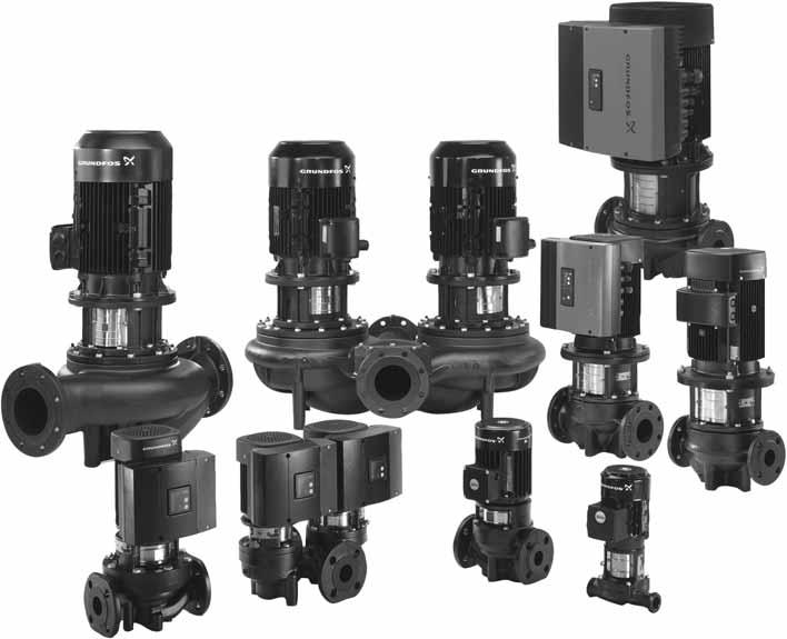
1 GRUNDFOS DATA BOOKLET TP, TPD, TPE, TPED In-line circulator pumps 5 Hz
2 TP, TPD, TPE, TPED Contents 1. Pump data 3 Introduction 3 Type key. Performance range 5 Performance range, -pole, PN 6, 1, 16 5 Performance range, -pole, PN 6, 1, 16 6 Performance range, 6-pole, PN 16 7 Performance range, -pole, PN 5 Performance range, -pole, PN Product range 1 Product range, -pole, PN 6, 1, 16 1 Product range, -pole, PN 6, 1, 16 1 Product range, 6-pole, PN 16 1 Product range, -pole, PN 5 1 Product range, -pole, PN Operating conditions 16 Ambient temperature Pumped liquids 17 Pumped liquids 17 Liquid temperature 17 List of pumped liquids 1 1. Curve charts How to read the curve charts Curve conditions Technical data/performance curves 5 TP, TPD, TPE, TPED, -pole, PN 6, 1, Technical data/performance curves 7 TP, TPD, TPE, TPED, -pole, PN 6, 1, Technical data/performance curves 1 TP, TPD, TPE, TPED, 6-pole, PN Technical data/performance curves 1 TP, -pole, PN Technical data/performance curves 11 TP, -pole, PN Weights and shipping volume 1 TP, TPD, TPE, TPED, -pole, PN 6, 1, 16 1 TP, TPD, TPE, TPED, -pole, PN 6, 1, TP, TPD, 6-pole, PN 6, 1, TP, -pole, PN 5 17 TP, -pole, PN TP Series 1 and pumps 7. TP Series 3 pumps. TP Series pumps 9. TPE Series 1 pumps 6 1. TPE Series pumps 11. Communication 3 Communication with TPE, TPED pumps 3 1. Speed regulation of TPE pumps 31 Affinity equations TP, TPE pumps in parallel 3 Control of TP, TPE pumps connected in parallel 3 1. Grundfos CUE 3 TP pumps connected to Grundfos CUE, external frequency converters Motor data 35 Motors 35 Motor protection 36 Electrical data, mains-operated motors 37 Electrical data, speed-controlled motors Installation Mechanical installation Electrical installation Flanges for TP pumps 7 Flange dimensions 7 5. Accessories 19 Unions and valves 19 Counter flanges 13 Base plates 133 Blanking flanges 135 Insulating kits 139 Sensors 1 Potentiometer 11 R1 11 CIU communication interface units 11 CIM communication interface modules 1 EMC filter 1 6. Minimum inlet pressure - NPSH 13 TP, TPD, -pole, PN 6, 1, 16 1 TP, TPD, -pole, PN 6, 1, TP, TPD, 6-pole, PN TP Series, -pole, PN 5 15 TP Series, -pole, PN Further product documentation 17 WebCAPS 17 WinCAPS 1
3 TP, TPD, TPE, TPED 1 1. Pump data Introduction TP pumps are designed for applications such as district heating systems heating systems air-conditioning systems district cooling systems water supply industrial processes industrial cooling. The pumps are available with either mains-operated motors (TP and TPD) or electronically speed-controlled motors (TPE and TPED). The pumps are all single-stage, in-line centrifugal pumps with mechanical shaft seal. The pumps are of the close-coupled type, i.e. pump and motor are separate units. Consequently, the pumps are less sensitive to impurities in the pumped liquid than similar pumps of the canned rotor type. TP, mains-operated pumps The TP range is divided into the following four groups based on their construction: TP Series 1,, 3 and. TP Series 1 with union or flange connection Rp 1 (DN 5) to Rp 1 1/ (DN 3) and motor sizes from.1 to.5 kw. For further information, see page. TP Series with flange connection DN 3 to DN 1 and motor sizes from.1 to. kw. For further information, see page. TP Series 3 with flange connection DN 3 to DN and motor sizes from.5 to 13 kw. For further information, see page. TP Series with flange connection Grundfos offers two TP Series versions: 1 bar version with DN 5 flange and motor sizes from 5 to 75 kw. 5 bar version with DN 1 to DN and motor sizes from 5.5 to 63 kw. For further information, see page. TPE, speed-controlled pumps Based on the construction and choice of material of TP pumps, Grundfos offers the following two series of speed-controlled TPE pumps: TPE Series 1 pumps (without factory-fitted differential-pressure sensor) TPE Series pumps (with factory-fitted differential-pressure sensor) TPE Series 1 pumps The difference between the TP and the TPE Series 1 pump range is the motor. The motors of TPE Series 1 pumps have built-in frequency converter. Via an external signal (from a sensor or a controller), TPE Series 1 pumps allow for any configuration and control method required: Constant pressure, temperature or flow. For further information, see page 6. TPE Series pumps The main differences between the TP and the TPE Series pumps are the motor and the factory-fitted differential-pressure sensor. TPE Series pumps are factory-set to proportional-pressure control. The motors of TPE Series pumps have built-in frequency converter for continuous adjustment of the pressure to the flow rate. The TPE Series range is recognized as a preset solution for quick and safe installation. For further information, see page. Why select a TPE pump? A TPE pump with electronic speed control offers these obvious benefits: energy savings increased comfort control and monitoring of pump performance communication with the pump. ATEX-approved TP pumps On request, Grundfos offers TP and TPD pumps with ATEX-approval. All ATEX-approved TP pumps are in accordance with Council directive 9/9/EC (Group II, category 3). If an ATEX-approved dry-running protection is installed, the pump can be upgraded to category G. High-efficiency motors TP pumps are fitted with high-efficiency motors. TP pumps are primarily fitted with motors that meet the legislative requirements of the EuP IE3 grade. For further information, see section Motors on pages 35 to 39. IE3 Pump data 3
4 1 TP, TPD, TPE, TPED Pump data Type key Example TP E D 65-1 / -S -A -F -A -BUBE Pump range Electronically speed-controlled pump (Series 1, ) Twin-head pump Nominal diameter of suction and discharge ports (DN) Maximum head [dm] Pole number S = TPE Series (with factory-fitted differential pressure sensor) Code for pump version: A = Basic version I = PN 6 flange X = Special version Code for pipework connection: F = DIN flange O = Union Code for materials: A = Basic version Z = Bronze pump housing and pump head B = Bronze impeller Code for shaft seal (incl. other plastic and rubber pump parts, except the neck ring) Codes for shaft seal Example B U B E Grundfos type designation A = O-ring seal with fixed seal driver B = Rubber bellows seal D = O-ring seal, balanced G = Bellows seal with reduced seal faces R = O-ring seal with reduced seal faces Material of rotating face A = Carbon, antimony-impregnated B = Carbon, resin-impregnated Q = Silicon carbide U = Tungsten carbide Material of stationary seat B = Carbon, resin-impregnated Q = Silicon carbide U = Tungsten carbide Material of secondary seal E = EPDM P = NBR rubber V = FKM
5 TP, TPD, TPE, TPED. Performance range Performance range, -pole, PN 6, 1, 16 (See page 5 for performance curves) TP(D), TPE(D) PN 6/1/16, -pole, 5 Hz Performance range p [kpa] TM Q [m³/h] H Q [l/s] R R R R Note: All QH curves apply to single-head pumps. For further information about curve conditions, see page 9. The hatched area shows the performance range of TPE pumps. 5
6 TP, TPD, TPE, TPED Performance range Performance range, -pole, PN 6, 1, 16 (See page 7 for performance curves) TP(D), TPE(D) PN 6/1/16, -pole, 5 Hz TM Q [m³/h] Q [l/s] H p [kpa] Note: All QH curves apply to single-head pumps. For further information about curve conditions, see page 9. The hatched area shows the performance range of TPE pumps. 6
7 TP, TPD, TPE, TPED Performance range, 6-pole, PN 16 (See page 1 for performance curves) TP(D) PN 16, 6-pole, 5 Hz 15-17/6 15-1/ /6 p [kpa] H 15-9/ /6 15-9/6 Performance range TM Q [m³/h] Q [l/s] /6 15-7/6 15-6/6 15-6/6 Note: All QH curves apply to single-head pumps. For further information about curve conditions, see page 9. 7
8 TP, TPD, TPE, TPED Performance range Performance range, -pole, PN 5 (See page 1 for performance curves) TP PN 5, -pole, 5 Hz p [kpa] H TM Q [m³/h] Q [l/s]
9 TP, TPD, TPE, TPED Performance range, -pole, PN 5 (See page 11 for performance curves) TP PN 5, -pole, 5 Hz p [kpa] Q [m³/h] Performance range TM H Q [l/s]
10 3 TP, TPD, TPE, TPED Product range 3. Product range Product range, -pole, PN 6, 1, 16 Design Shaft seal Pressure stage Materials Mains-operated motor Electronically speed-controlled motor Pump housing Impeller Voltage [V] Voltage [V] Pump type TPE Series 1 TPE Series TP Series 1 TP Series TP Series 3 TP Series BUBE AUUE RUUE BAQE BQQE GQQE DBUE PN 6 PN 1 PN 16 PN 5 Cast iron EN-GJL-5 Nodular cast iron EN-GJS--1 Bronze 1) TP 5-5/ R TP 5-9/ R TP 3-5 / R TP 3-9/ R TP, TPD 3-6/ TP, TPD 3-1/ TP, TPD 3-15/ TP, TPD 3-1/ TP, TPD 3-3/ TP, TPD 3-/ TP, TPD 3-5/ TP, TPD 3-3/... TP, TPD 3-3/ TP, TPD 3-6/... TP, TPD 3-5/ TP -5/ TP, TPD -6/ TP -9/ TP, TPD -1/ TP -1/ TP, TPD -19/ TP, TPD -3/ TP, TPD -7/ TP, TPD -/... TP, TPD -3/ TP, TPD -36/... TP, TPD -7/ TP, TPD -5/ TP, TPD 5-6/ TP, TPD 5-1/ TP, TPD 5-1/ TP, TPD 5-16/ TP, TPD 5-19/ TP, TPD 5-/... TP, TPD 5-9/ TP, TPD 5-36/... TP, TPD 5-3/ TP, TPD 5-/ TP, TPD 5-57/ TP, TPD 5-71/ TP, TPD 5-3/ TP, TPD 5-9/... TP, TPD 65-6/ TP, TPD 65-1/ TP, TPD 65-1/ TP, TPD 65-19/... TP, TPD 65-3/ TP, TPD 65-6/... TP, TPD 65-3/ TP, TPD 65-1/ TP, TPD 65-6/ TP, TPD 65-55/ TP, TPD 65-66/ TP, TPD 65-7/... Stainless steel Cast iron Nodular cast iron EN-GJS--15 Bronze 1 x -3 ΔV/ YV P 3 x - ΔV/ 3-15 YV P 3 x 3-15 ΔV/ YV ) P 1 x - V P 3 x 3- V P 1
11 TP, TPD, TPE, TPED 3 Pump type TPE Series 1 Design Shaft seal Pressure stage TPE Series TP Series 1 TP Series TP Series 3 TP Series BUBE AUUE RUUE BAQE BQQE GQQE DBUE PN 6 PN 1 PN 16 PN 5 Materials Mains-operated motor Electronically speed-controlled motor Pump housing Impeller Voltage [V] Voltage [V] TP, TPD 65-93/ TP, TPD -1/ TP, TPD -1/... TP, TPD -1/ TP, TPD -1/... TP, TPD -/ TP, TPD -5/ TP, TPD -33/ TP, TPD -/ TP, TPD -5/ TP, TPD -57/... TP, TPD -7/ TP, TPD 1-1/... TP, TPD 1-16/... TP, TPD 1-/ TP, TPD 1-/ TP, TPD 1-5/ TP, TPD 1-31/ TP, TPD 1-36/ TP, TPD 1-39/... TP, TPD 1-/ Cast iron EN-GJL-5 Nodular cast iron EN-GJS--1 Bronze 1) Stainless steel Cast iron Nodular cast iron EN-GJS--15 Bronze 1 x -3 ΔV/ YV P 3 x - ΔV/ 3-15 YV P 3 x 3-15 ΔV/ YV ) P 1 x - V P 3 x 3- V P Product range Standard. 1) Bronze versions are only available as single-head pumps. ) -pole motors above 5.5 kw can be operated at 3 x YV. Smaller motor sizes cannot. 11
12 3 TP, TPD, TPE, TPED Product range Product range, -pole, PN 6, 1, 16 Pump type TPE Series 1 Design Shaft seal Pressure stage TPE Series TP Series 1 TP Series TP Series 3 TP Series BUBE AUUE RUUE BAQE BQQE GQQE DBUE PN 6 PN 1 PN 16 PN 5 Materials Mains-operated motor Electronically speed-controlled motor Pump housing Impeller Voltage [V] Voltage [V] Cast iron EN-GJL-5 Nodular cast iron EN-GJS--1 Bronze 1) TP, TPD 3-3/ TP, TPD 3-/ TP, TPD 3-6/ TP, TPD 3-/ TP, TPD 3-1/ TP, TPD 3-1/ TP, TPD -3/ TP -6/ TP, TPD -9/ TP, TPD -1/ TP, TPD -13/ TP, TPD -16/ TP, TPD 5-3/ TP, TPD 5-6/ TP, TPD 5-9/ TP, TPD 5-11/ TP, TPD 5-13/ TP, TPD 5-16/ TP, TPD 5-19/... TP, TPD 5-3/ TP, TPD 65-3/ TP, TPD 65-6/ TP, TPD 65-9/ TP, TPD 65-11/ TP, TPD 65-13/ TP, TPD 65-15/... TP, TPD 65-17/ TP, TPD 65-/... TP, TPD -3/ TP, TPD -6/ TP, TPD -7/ TP, TPD -9/ TP, TPD -11/... TP, TPD -15/ TP, TPD -17/... TP, TPD -/ TP, TPD -7/ TP, TPD -3/ TP, TPD 1-3/ TP, TPD 1-6/ TP, TPD 1-7/ TP, TPD 1-9/... TP, TPD 1-11/ TP, TPD 1-13/... TP, TPD 1-17/ TP, TPD 1-/ TP, TPD 1-5/ TP, TPD 1-33/ TP, TPD 1-37/ TP, TPD 1-1/.. TP 15-7/... TP 15-9/ TP 15-1/... TP, TPD 15-11/... TP, TPD 15-13/ TP, TPD 15-16/ TP, TPD 15-1/ TP, TPD 15-5/ Stainless steel Cast iron Nodular cast iron EN-GJS--15 Bronze 1 x -3 ΔV/ YV P 3 x - ΔV/ 3-15 YV P 3 x 3-15 ΔV/ YV ) P 1 x - V P 3 x 3- V P 1
13 TP, TPD, TPE, TPED 3 Pump type TPE Series 1 Design Shaft seal Pressure stage TPE Series TP Series 1 TP Series TP Series 3 TP Series BUBE AUUE RUUE BAQE BQQE GQQE DBUE PN 6 PN 1 PN 16 PN 5 Materials Mains-operated motor Electronically speed-controlled motor Pump housing Impeller Voltage [V] Voltage [V] TP, TPD 15-3/ TP, TPD 15-36/.. TP, TPD 15-/ TP 15-1/ TP, TPD 15-13/ TP 15-1/ TP 15-15/ TP, TPD 15-16/ TP, TPD 15-/ TP, TPD 15-/ TP, TPD 15-5/.. TP 15-6/ TP 15-/.. TP 15-3/ TP 15-39/ 37. TP 15-5/ TP 15-5/ TP 15-66/ TP 15-6/ TP -5/... TP -7/ TP -9/ TP -13/ TP -15/ TP -16/ TP -19/ TP -/.. TP -/ TP -7/ 5. TP -9/ 37. TP -3/ 55. TP -33/ 37. TP -36/ 5. TP -/ 55. TP -1/ 75. TP -7/ 75. TP -53/ 9. TP -59/ 11 TP -66/ 13 TP 5-/ 5. TP 5-31/ 55. TP 5-39/ 75. Cast iron EN-GJL-5 Nodular cast iron EN-GJS--1 Bronze 1) Stainless steel Cast iron Nodular cast iron EN-GJS--15 Bronze 1 x -3 ΔV/ YV P 3 x - ΔV/ 3-15 YV P 3 x 3-15 ΔV/ YV ) P 1 x - V P 3 x 3- V P Product range Standard. 1) Bronze versions are only available as single-head pumps. ) -pole motors above kw can be operated at 3 x YV. Smaller motor sizes cannot. 13
14 3 TP, TPD, TPE, TPED Product range Product range, 6-pole, PN 16 Pump type TPE Series 1 Design Shaft seal Pressure stage TPE Series TP Series 1 TP Series TP Series 3 TP Series BUBE AUUE RUUE BAQE BQQE GQQE DBUE PN 6 PN 1 PN 16 PN 5 Materials Mains-operated motor Electronically speed-controlled motor Pump housing Impeller Voltage [V] Voltage [V] Cast iron EN-GJL-5 Nodular cast iron EN-GJS--1 Bronze 1) TP, TPD 15-6/6 1.5 TP, TPD 15-7/6.. TP, TPD 15-9/ TP, TPD 15-11/6.. TP, TPD 15-1/ TP, TPD 15-17/ TP, TPD 15-6/6.. TP, TPD 15-7/ TP, TPD 15-9/6.. TP, TPD 15-11/ Stainless steel Cast iron Nodular cast iron EN-GJS--15 Bronze 1 x -3 ΔV/ YV P 3 x - ΔV/ 3-15 YV P 3 x 3-15 ΔV/ YV P 1 x - V P 3 x 3- V P 3 x 3-15 V P Standard. 1) Bronze versions are only available as single-head pumps. Product range, -pole, PN 5 Design Shaft seal Pressure stage Materials Mains-operated motor Electronically speed-controlled motor Pump housing Impeller Voltage [V] Voltage [V] Pump type TPE Series 1 TPE Series TP Series 1 TP Series TP Series 3 TP Series BUBE AUUE RUUE BAQE BQQE GQQE DBUE PN 6 PN 1 PN 16 PN 5 Cast iron EN-GJL-5 Nodular cast iron EN-GJS--1 Bronze Stainless steel Cast iron TP 1-6/ 37. TP 1-7/ 5. TP 1-/ 55. TP 1-96/ 75. TP 1-15/ 75. TP 1-11/ 9. TP 1-1/ 11. TP 1-153/ 13. TP 1-16/ 16. Nodular cast iron EN-GJS--15 Bronze 1 x -3 ΔV/ YV P 3 x - ΔV/ 3-15 YV P 3 x 3-15 ΔV/ YV P 1 x - V P 3 x 3- V P 3 x 3-15 V P Standard. 1
15 TP, TPD, TPE, TPED 3 Product range, -pole, PN 5 Pump type Standard. Design Shaft seal Pressure stage TPE Series 1 TPE Series TP Series 1 TP Series TP Series 3 TP Series BUBE AUUE RUUE BAQE BQQE GQQE DBUE PN 6 PN 1 PN 16 PN 5 Materials Mains-operated motor Electronically speed-controlled motor Pump housing Impeller Voltage [V] Voltage [V] Cast iron EN-GJL-5 Nodular cast iron EN-GJS--1 Bronze Stainless steel Cast iron TP 1-19/ 5.5 TP 1-/ 7.5 TP 1-6/ 11. TP 1-7/ 11. TP 1-3/ 15. TP 1-3/ 1.5 TP 1-/. TP 15-15/ 7.5 TP 15-/ 11. TP 15-/ 15. TP 15-/ 15. TP 15-31/ 1.5 TP 15-37/. TP 15-3/ 3. TP 15-/ 1.5 TP 15-7/. TP 15-3/ 3. TP 15-35/ 37. TP 15-3/ 5. TP 15-53/ 55. TP 15-65/ 75. TP -6/ 3. TP -/ 37. TP -3/ 5. TP -/ 55. TP -5/ 55. TP -51/ 75. TP -56/ 9. TP -6/ 11. TP 5-7/ 5. TP 5-3/ 55. TP 5-37/ 75. TP 5-9/ 9. TP 5-5/ 11. TP 5-6/ 13. TP 5-66/ 16. TP 3-59/. TP 3-67/ 5. TP 3-75/ 315. TP -7/ 315. TP -51/ 355. TP -5/. TP -67/ 5. TP -7/ 56. TP -76/ 63. Nodular cast iron EN-GJS--15 Bronze 1 x -3 ΔV/ YV P 3 x - ΔV/ 3-15 YV P 3 x 3-15 ΔV/ YV P 1 x - V P 3 x 3- V P Product range 15
16 TP, TPD, TPE, TPED Operating conditions. Operating conditions System and test pressures System pressure Test pressure Pressure [bar] [MPa] [bar] [MPa] PN PN PN PN Sound pressure level Single-phase: Three-phase: Max. 7 db(a). See table below. Maximum sound pressure level [db(a)] - ISO 373 Motor Three-phase motors -pole -pole 6-pole The audible noise from TP pumps is primarily noise from the motor fan. The selection of TPE pumps will reduce the noise at partial load, as the motor, and consequently, the motor fan runs at a lower speed. Possible flow noise from control valves is also reduced at partial load in the case of the TPE pump. Ambient temperature MG IE and IE3 motors:.75 - kw motors, -pole -3 to +6 C kw motors, -pole Siemens IE and IE3 motors: 3-9 kw motors, -pole -3 to +55 C kw motors, -pole MGE and other motor sizes -3 to + C Storage Down to -3 C If the ambient temperature exceeds above maximum values or if the motor is located more than 1 metres above sea level, the motor output (P ) must be reduced due to the low density and consequent low cooling effect of the air. In such cases, it may be necessary to use an oversize motor with a higher rated output. [%] t [ C] m Fig. 1 Relationship between motor output (P ) and altitude Key Pos. Description Siemens IE and IE3 motors: kw motors, -pole kw motors, -pole MG IE and IE3 motors:.75 - kw motors, -pole kw motors, -pole 3 MGE and other motor sizes TM The values apply only to MG and Siemens motors. The values have a tolerance of 3 db according to EN ISO 71; the tolerance is not added to the values in the table. 16
17 TP, TPD, TPE, TPED 5 5. Pumped liquids Pumped liquids Thin, clean, non-aggressive and non-explosive liquids, not containing solid particles or fibres that may mechanically or chemically attack the pump. See "List of pumped liquids" on page 1. Examples of liquids Central heating system water (the water should meet the requirements of accepted standards on water quality in heating systems) cooling liquids domestic hot water industrial liquids softened water. If glycol or another antifreeze agent is added to the pumped liquid, the pump must have a shaft seal of the type RUUE or GQQE. The pumping of liquids with densities or kinematic viscosities higher than those of water can have these consequences: a considerable pressure drop a drop in the hydraulic performance a rise in the power consumption. In these situations, equip the pump with an oversize motor. If in doubt, contact Grundfos. If the water contains mineral oils or chemicals, or if other liquids than water are pumped, the O-rings should be chosen accordingly. Liquid temperature Liquid temperature: -5 C to +15 C. Please note that shaft seals operating close to their maximum temperature will require regular maintenance, i.e. replacement. Pump type Shaft seal Temperature TP Series 1 TP Series TP Series 3 TP Series, 1 bar version TP Series, 5 bar version BUBE C to +11 C BQQE C to +9 C GQQE -5 C to +9 C BUBE C to +1 C AUUE C to +9 C RUUE -5 C to +9 C BAQE C to +1 C (1 C) 1) BQQE C to +9 C GQQE -5 C to +9 C (6 C) ) 1) TP Series 3 pumps are designed for a maximum operating temperature of 1 C. For operation above 1 C, an alternative shaft seal is to be selected. Contact Grundfos. ) The below listed TP Series 3 pumps with GQQE shaft seals are designed for a maximum operating temperature of 6 C. TP 15-6/ TP -16/ TP 15-/ TP -19/ TP 15-3/ TP -/ TP 15-39/ TP -/ TP 15-5/ TP -7/ TP 15-5/ TP -9/ TP 15-66/ TP -3/ TP 15-6/ TP -33/ TP -36/ TP -/ TP -1/ TP -7/ TP -53/ TP -59/ TP -66/ BAQE C to +1 C BQQE C to +9 C GQQE -5 C to +9 C DBUE C to +15 C 3) Pumped liquids 3) At +1 to +15 C, the maximum operating pressure 3 bar. Depending on the type of cast iron used and the pump application, the maximum liquid temperature may be limited by local regulations and laws. 17
18 5 TP, TPD, TPE, TPED Pumped liquids List of pumped liquids Grundfos TP and TPD pumps are designed for circulation systems with constant flow; TPE and TPED pumps for systems with variable flow. Thanks to their design, the pumps can be used in a wider liquid temperature range than pumps of the canned rotor type. A number of typical liquids are listed below. Other pump versions may be used, but we consider the ones stated in the list to be the best choices. The list is intended as a general guide only, and it cannot replace actual testing of the pumped liquids and pump materials under specific working conditions. If in doubt, contact Grundfos. Use the list with some caution, as factors such as concentration of the pumped liquid, liquid temperature or pressure may affect the chemical resistance of a specific pump version. Legend May contain additives or impurities that may cause shaft seal A problems. The density and/or viscosity differ from those of water. B Consider this when calculating motor and pump performance. C The liquid must be oxygen-free (anaerobic). D Risk of crystallisation/precipitation in the shaft seal. E Insoluble in water. F The shaft seal rubber parts must be replaced with FKM rubber. G Bronze housing/impeller required. H Risk of formation of ice on the standby pump. (The risk only applies to TP, TPE Series pumps.) Pumped liquids Water Groundwater Notes Additional information Shaft seal TP Series 1 TP Series TP Series 3 < +9 C BQQE AUUE BQQE > +9 C BUBE BUBE BAQE 1) BBQE ) TP Series PN 1 BAQE TP Series PN 5 < +1 C BUBE 3) BUBE BAQE BAQE DBUE Boiler-feed water < +1 C BUBE BQBE/DAQF ) DBUE < +15 C DBUE District heating water < +1 C BUBE BUBE BAQE BAQE DBUE Condensate < +9 C BQQE AUUE BQQE > +9 C BUBE BUBE BAQE BAQE DBUE Softened water C < +9 C BQQE AUUE BQQE > +9 C BUBE BUBE BAQE BAQE DBUE Brackish water Coolants Ethylene glycol B, D, H < +5 C, 5 % Glycerine (glycerol) B, D, H < +5 C, 5 % Potassium acetate B, D, C, H < +5 C, 5 % Potassium formate B, D, C, H < +5 C, 5 % Propylene glycol G B, D, H Brine-sodium chloride B, D, C, H < +5 C, 3 % Synthetic oils Silicone oil B, E ph > 6.5, + C, 1 ppm Cl - BUBE BQQE BQQE GQQE BQQE GQQE BQQE GQQE BQQE GQQE BQQE GQQE BQQE GQQE BUBE BQQE BUBE AUUE AUUE RUUE AUUE RUUE AUUE RUUE AUUE RUUE AUUE RUUE AUUE RUUE BUBE AUUE DBUE BQQE BQQE DBUE BQQE GQQE BQQE GQQE BQQE GQQE BQQE GQQE BQQE GQQE BQQE GQQE BAQE BQQE GQQE DQQE ) GQQE DQQE ) GQQE DQQE ) GQQE DQQE ) GQQE DQQE ) GQQE DQQE ) BAQE DBUE (To be continued) 1
19 TP, TPD, TPE, TPED 5 Pumped liquids Vegetable oils Corn oil B, F, E Olive oil B, F, E < + C Peanut oil Rape seed oil Soya bean oil Cleaning agents B, F, E D, B, F, E B, F, E Soap (salts of fatty acids) A, E, (F) < + C Alkaline degreasing agent A, E, (F) < + C Oxidants Notes Additional information Hydrogen peroxide < + C, < % BUBV ) BUBV ) BAQV ) BQQV ) AUUV ) BQQV ) BAQV ) DBUV ) BUBV ) BUBV ) BAQV ) BQQV ) AUUV ) BQQV ) BAQV ) DBUV ) BUBV ) BUBV ) BAQV ) BQQV ) AUUV ) BQQV ) BAQV ) DBUV ) BUBV ) BUBV ) BAQV ) BQQV ) AUUV ) BQQV ) BAQV ) DBUV ) BUBV ) BUBV ) BAQV ) BQQV ) AUUV ) BQQV ) BAQV ) DBUV ) BQQE (BQQV) ) BQQE (BQQV) ) BUBE BQQE AUUE (AUUV) ) AUUE (AUUV) ) BUBE AUUE Shaft seal TP Series 1 TP Series TP Series 3 TP Series PN 1 TP Series PN 5 BQQE (BQQV) ) GQQE DQQE ) BQQE (BQQV) ) GQQE DQQE ) BQQE BQQV ) DQQE ) Salts Ammonium bicarbonate A < + C, < 15 % BQQE AUUE BQQE GQQE DQQE ) Calcium acetate A, B < + C, < 3 % BQQE AUUE BQQE GQQE DQQE ) Potassium bicarbonate A < + C, < % BQQE AUUE BQQE GQQE DQQE ) Potassium carbonate A < + C, < % BQQE AUUE BQQE GQQE DQQE ) Potassium permanganate A < + C, < 1 % BQQE AUUE BQQE GQQE DQQE ) Potassium sulphate A < + C, < % BQQE AUUE BQQE GQQE DQQE ) Sodium acetate A < + C, < 1 % BQQE AUUE BQQE GQQE DQQE ) Sodium bicarbonate A < + C, < % BQQE AUUE BQQE GQQE DQQE ) Sodium carbonate A < + C, < % BQQE AUUE BQQE GQQE DQQE ) Sodium nitrate A < + C, < % BQQE AUUE BQQE GQQE DQQE ) Sodium nitrite A < + C, < % BQQE AUUE BQQE GQQE DQQE ) Sodium phosphate (di) A < +1 C, < 3 % BQQE AUUE BQQE GQQE DQQE ) Sodium phosphate (tri) A < +9 C, < % BQQE AUUE BQQE GQQE DQQE ) Sodium sulphate A < + C, < % BQQE AUUE BQQE GQQE DQQE ) Sodium sulphite A < + C, < 1 % BQQE AUUE BQQE GQQE DQQE ) Alkalis Ammonium hydroxide < +1 C, < 3 % BQQE AUUE BQQE GQQE DQQE ) Calcium hydroxide A < +1 C, < 1 % BQQE AUUE BQQE GQQE DQQE ) Potassium hydroxide A < + C, < % BQQE AUUE BQQE GQQE DQQE ) Sodium hydroxide A < + C, < % BQQE AUUE BQQE GQQE DQQE ) Pumped liquids 1) BAQE must not be used for potable water. For potable water, Grundfos recommends a BBQE shaft seal. ) The shaft seal is not standard, but available on request. 3) Maximum +11 C. 19
: -5 to +11 C Liquid temperature (TP Series ): -5 to +1 C Maximum operating")

20 6 TP, TPD, TPE, TPED TP Series 1 and pumps 6. TP Series 1 and pumps Fig. TP Series 1 and TP Series Technical data Flow rate: Up to 9 m 3 /h Head: Up to 7 m Liquid temperature (TP Series 1): -5 to +11 C Liquid temperature (TP Series ): -5 to +1 C Maximum operating pressure: Up to 16 bar Direction of rotation: Counter-clockwise Construction Grundfos TP Series 1 and Series pumps are single-stage, close-coupled pumps with in-line suction and discharge ports of identical diameter. The pumps are fitted with a fan-cooled asynchronous motor. Motor and pump shafts are connected via a rigid two-part coupling. TP Series 1 pumps with union connection are available as single-head (TP) pumps. TP Series pumps are available as single-head (TP) and twin-head (TPD) pumps. TP Series pumps have PN 6 or PN 1 flanges. The pumps are fitted with an unbalanced mechanical shaft seal. The pumps are of the top-pull-out design, i.e. the power head (motor, pump head and impeller) can be removed for maintenance or service while the pump housing remains in the pipework. The twin-head pumps are designed with two parallel power heads. A non-return flap valve in the common discharge port is opened by the flow of the pumped liquid and prevents backflow of liquid into the idle pump head. As radial and axial forces are absorbed by the fixed bearing in the motor drive-end, the pump requires no bearing. TP, TPD Series 1 and pumps are fitted with high-efficiency motors. Pumps with bronze pump housing (version B) are suitable for circulation of domestic hot water. Gr6 - Gr61 Materials TP Series 1 Fig. 3 Sectional drawing of TP Series 1 (with union connection) Material specification, Series 1 Pos. Component Material EN/DIN 1 Pump housing TP, TPE Series Cast iron EN-GJL-, bronze CuSn1 Fig. Sectional drawing of TP Series (with flange connection) TM EN-JL Impeller Stainless steel Shaft Stainless steel 1.57 Coupling Cast iron EN-GJL-.7 5 Pump head Cast iron EN-GJL-5, bronze Secondary seals EPDM Rotating seal face Stationary seat Tungsten carbide Silicon carbide 5 3 Carbon (resin-impregnated) Silicon carbide TM
21 TP, TPD, TPE, TPED 6 Material specification, Series Pos. Component Material EN/DIN 1 Pump housing Cast iron EN-GJL-5, bronze CuSn1 EN-JL Impeller Stainless steel Shaft Stainless steel 1.35 Coupling Cast iron EN-GJL-.7 5 Pump head Cast iron EN-GJL-5, bronze Secondary seals EPDM Rotating seal face Tungsten carbide Stationary seat Carbon (resin-impregnated) Tungsten carbide Connections TP Series 1 pumps with union connection have suction and discharge union threads to ISO -1. TP Series pumps up to DN 65 are fitted with combination flanges PN 6/PN 1. DN or DN 1 pumps have either PN 6 or PN 1 flanges. All flanges can be connected to flanges in accordance with EN 19- and ISO 75-. Features and benefits TP Series 1 and Series pumps have these features and benefits: TP Series 1 and pumps Mechanical shaft seal Three types of unbalanced mechanical shaft seal are available as standard: BUBE The BUBE shaft seal is a Grundfos rubber bellows seal with tungsten carbide/carbon seal faces and secondary seals of EPDM. RUUE/GQQE The RUUE shaft seal is a Grundfos O-ring seal with reduced tungsten carbide/tungsten carbide seal faces and secondary seals of EPDM. The GQQE shaft seal is a Grundfos rubber bellows seal with reduced silicon carbide/silicon carbide seal faces and secondary seals of EPDM. AUUE/BQQE The AUUE shaft seal is a Grundfos O-ring seal with fixed seal driver, tungsten carbide/tungsten carbide seal faces and secondary seals of EPDM. The BQQE shaft seal is a Grundfos rubber bellows seal with silicon carbide/silicon carbide seal faces and secondary seals of EPDM. Information on a selection of common pumped liquids with recommended shaft seals is shown on page 1. Shaft seal specification Unbalanced shaft seal Shaft diameter Rubber bellows Seal faces TP Series 1 TP, TPD Series Version KU according to EN 1756 Version NU according to EN and 16 mm EPDM Tungsten carbide/carbon Tungsten carbide/tungsten carbide Silicon carbide/silicon carbide Special shaft seals are available for partly conditioned water or other liquids containing abrasive or crystallising particles. See page 1. Optimised hydraulics for high efficiency - Reduced power consumption. High-efficiency motors - TP pumps are fitted with high-efficiency motors. High-efficiency motors offer reduced energy consumption. TP pumps are primarily fitted with motors that meet the legislative requirements of the EuP IE3 grade. For further information, see section Motors on pages 35 to 39. Top-pull-out design - Easy dismantling in case of service. In-line design - Contrary to end-suction pumps, in-line pumps allow a straight pipework and thus often reduced installation costs. Pump housing and pump head are electrocoated to improve the corrosion resistance - Electrocoating includes: 1. Alkaline cleaning.. Pretreatment with zinc phosphate coating. 3. Cathodic electrocoating (epoxy).. Curing of paint film at -5 C. For low-temperature applications at a high humidity, Grundfos offers TP pumps with extra surface treatment to avoid corrosion. These pumps are available on request. Stainless-steel impeller and neck ring - Wear-free operation with high efficiency. TPE, TPED - pumps with built-in frequency converter - -pole and -pole TP pumps from.37 and upwards are available as TPE pumps with built-in frequency converter. See pages 3 and

22 7 TP, TPD, TPE, TPED TP Series 3 pumps 7. TP Series 3 pumps TP Series 3 pumps with bronze impeller are suitable for pumping brine. Materials Fig. 5 TP Series 3 Gr59 TM Technical data Flow rate: Up to 5 m 3 /h Head: Up to 93 m Liquid temperature: -5 to +1 C Maximum operating pressure: 16 bar Direction of rotation: Clockwise Construction Grundfos TP, TPD Series 3 pumps are single-stage, close-coupled pumps with in-line suction and discharge ports of identical diameter. The pumps are fitted with a fan-cooled asynchronous motor. Motor and pump shafts are connected via a rigid sleeve coupling. Most TP Series 3 pumps are available as single-head (TP) and twin-head (TPD) pumps. TP Series 3 pumps have PN 16 flanges. The pumps are fitted with an unbalanced mechanical shaft seal. The pumps are of the top-pull-out design, i.e. the power head (motor, pump head and/or motor stool and impeller) can be removed for maintenance or service while the pump housing remains in the pipework. The pump housing is provided with replaceable wear rings to ensure high pump efficiency for life. The twin-head pumps are designed with two parallel power heads. A non-return flap valve in the common discharge port is opened by the flow of the pumped liquid and prevents backflow of liquid into the idle pump head. As radial and axial forces are absorbed by the fixed bearing in the motor drive-end, the pump requires no bearing. The impeller is hydraulically balanced to minimise axial forces. TP, TPD Series 3 pumps are fitted with high-efficiency motors. Fig. 6 Sectional drawing of TP Series 3 Material specification Pos. Component Material EN/DIN 1 Pump housing Cast iron EN-GJL-5 EN-JL 1 Impeller 3 Stub shaft Two-part stub shaft Pump head/motor stool Secondary seals Cast iron EN-GJL-, bronze CuSn5Zn5Pb Stainless steel Stainless steel/steel EN-JL /1.31 Cast iron EN-GJL-5 EN-JL 1 EPDM Metal-impregnated Rotating seal face carbon Silicon carbide Stationary seat Silicon carbide 5 Wear rings Bronze CuSn1.193
23 TP, TPD, TPE, TPED 7 Mechanical shaft seal Three types of unbalanced mechanical shaft seal are available as standard: BAQE The BAQE shaft seal is a Grundfos rubber bellows seal with carbon/silicon carbide seal faces and secondary seals of EPDM. GQQE The GQQE shaft seal is a Grundfos rubber bellows seal with reduced silicon carbide/silicon carbide seal faces and secondary seals of EPDM. BQQE The BQQE shaft seal is a Grundfos rubber bellows seal with silicon carbide/silicon carbide seal faces and secondary seals of EPDM. Information on a selection of common pumped liquids with recommended shaft seals is shown on page 1. Shaft seal specification Unbalanced shaft seal Version NU according to EN 1756 Shaft diameter, 3, and 55 mm Rubber bellows EPDM Seal faces Carbon/silicon carbide Silicon carbide/silicon carbide Special shaft seals are available for partly conditioned water or other liquids containing abrasive or crystallising particles. See page 1. Connections TP Series 3 pumps have PN 16 flanges. All dimensions are according to ISO 75- or EN 19-. Features and benefits TP Series 3 pumps have these features and benefits: Optimised hydraulics for high efficiency - Reduced power consumption. High-efficiency motors - TP pumps are fitted with high-efficiency motors. High-efficiency motors offer reduced energy consumption. TP pumps are primarily fitted with motors that meet the legislative requirements of the EuP IE3 grade. For further information, see section Motors on pages 35 to 39. Top-pull-out design - Easy dismantling in case of service. In-line design - Contrary to end-suction pumps, in-line pumps allow a straight pipework and thus often reduced installation costs. Motor-pump shaft with sleeve coupling - Stable and quiet operation. - Easy dismantling in case of service. Hydraulically and mechanically balanced impeller - The impeller is hydraulically and mechanically balanced to increase the life of motor bearings and shaft seal. Pump housing and pump head/motor stool are electrocoated to improve the corrosion resistance - Electrocoating includes: 1. Alkaline cleaning.. Pretreatment with zinc phosphate coating. 3. Cathodic electrocoating (epoxy).. Curing of paint film at -5 C. For low-temperature applications at a high humidity, Grundfos offers TP pumps with extra surface treatment to avoid corrosion. These pumps are available on request. TPE, TPED - pumps with built-in frequency converter - -pole TP pumps from.37 to kw and -pole TP pumps from.37 to 1.5 kw are available as TPE pumps with built-in frequency converter. See pages 3 and TP Series 3 pumps 3

24 TP, TPD, TPE, TPED TP Series pumps. TP Series pumps TP Series pumps are fitted with high-efficiency motors. Materials Gr7539 TM Fig. 7 TP Series Technical data Flow rate: PN 1 version: PN 5 version: Up to 95 m 3 /h Up to 5 m 3 /h Head: PN 1 version: PN 5 version: Up to 3 m Up to 17 m Liquid temperature: PN 1 version: PN 5 version: -5 to +1 C to +15 C * * From +1 to +15 C, max. 3 bar Maximum operating pressure: 1 bar version: 5 bar version: 1 bar 5 bar Direction of rotation: Clockwise Construction Grundfos TP Series pumps are single-stage, close-coupled pumps with in-line suction and discharge ports. The pumps are fitted with a fan-cooled asynchronous motor. Motor and pump shafts are connected via a rigid flange coupling. TP Series pumps are available as single-head (TP) pumps. All TP Series pumps have PN 1 or PN 5 flanges. The largest pumps have DN, PN discharge flanges and a maximum operating pressure of 5 bar. The pumps are fitted with an unbalanced mechanical shaft seal. The pumps are of the top-pull-out design, i.e. the power head (motor, motor stool and impeller) can be removed for maintenance or service while the pump housing remains in the pipework. The pump housing is provided with replaceable wear rings to ensure high pump efficiency for life. As radial and axial forces are absorbed by the fixed bearing in the motor drive-end, the pump requires no bearing. Fig. Sectional drawing of TP Series Material specification TP Series, PN 1 Pos. Component Material EN/DIN 1 Pump housing Cast iron EN-GJL-5 EN-JL1 Impeller Ductile cast iron EN-GJS- EN-JL13 Bronze Pump shaft Stainless steel 1.36 Coupling Cast iron EN-GJL-5 EN-JL1 5 Motor stool Cast iron EN-GJL-5 EN-JL1 Secondary seals EPDM rubber Metal-impregnated carbon Rotating seal face Silicon carbide Stationary seat Silicon carbide 6 Wear rings Bronze CuSn1.193 TP Series, PN 5 Pos. Component Material EN/DIN 1 Pump housing Ductile cast iron EN-GJS--1 (A-LT) EN-JS1 Impeller Ductile cast iron EN-GJS- EN-JS13 Bronze Pump shaft Stainless steel 1.36 Coupling Cast iron EN-GJL-5 EN-JL1 5 Motor stool Cast iron EN-GJL-5 EN-JL1 Secondary seals EPDM rubber Rotating seal face Resin-impregnated carbon Stationary seat Tungsten carbide
25 TP, TPD, TPE, TPED Mechanical shaft seal For 1 bar versions, the following three types of unbalanced mechanical shaft seal are available as standard: BAQE The BAQE shaft seal is a Grundfos rubber bellows seal with carbon/silicon carbide seal faces and secondary seals of EPDM. GQQE The GQQE shaft seal is a Grundfos rubber bellows seal with reduced silicon carbide/silicon carbide seal faces and secondary seals of EPDM. BQQE The BQQE shaft seal is a Grundfos rubber bellows seal with silicon carbide/silicon carbide seal faces and secondary seals of EPDM. For 5 bar versions, the following mechanical shaft seal is available as standard: DBUE The DBUE shaft seal is a Grundfos balanced O-ring seal with carbon/tungsten carbide seal faces and secondary seals of EPDM. Information on a selection of common pumped liquids with recommended shaft seals is shown on page 1. Special shaft seals are available for partly conditioned water or other liquids containing abrasive or crystallising particles. See page 1. Features and benefits TP Series pumps have the following features and benefits: Optimised hydraulics for high efficiency - Reduced power consumption. High-efficiency motors - TP pumps are fitted with high-efficiency motors. High-efficiency motors offer reduced energy consumption. TP pumps are primarily fitted with motors that meet the legislative requirements of the EuP IE3 grade. For further information, see section Motors on pages 35 to 39. Top-pull-out design - Easy dismantling in case of service. In-line design - Contrary to end-suction pumps, in-line pumps allow a straight pipework and thus often reduced installation costs. Motor-pump shaft with flange coupling - Stable and quiet operation. - Easy dismantling in case of service. Supported flange connection - Pump housing flanges have integrated feet in order to stabilise the pump. Surface treatment TP Series pumps are given the following surface treatment: TP Series pumps Connections TP Series pumps are the only TP pumps with suction and discharge ports of different diameters. The suction port is one dimension larger than the discharge port in order to obtain a low inlet velocity. This reduces risk of cavitation and noise. From DN 1 to DN 3 TP Series pumps have flanges according to ISO 75- or EN 19-. Pump type Electrocoating Spray painting TP Series (from DN 1 to DN 3) x x TP Series (DN ) x Electrocoating includes: 1. Alkaline cleaning.. Pretreatment with zinc phosphate coating. 3. Cathodic electrocoating (epoxy).. Curing of paint film at -5 C. For low-temperature applications at a high humidity, Grundfos offers TP pumps with extra surface treatment to avoid corrosion. These pumps are available on request. 5
 pumps up to 11 % speed). H H Fig.")
26 9 TP, TPD, TPE, TPED TPE Series 1 pumps 9. TPE Series 1 pumps TM Applications TPE Series 1 pumps have integrated speed control for automatic adaptation of performance to current conditions. The energy consumption is thus kept at a minimum. TPE Series 1 pumps can operate in any duty point within the range between 5 % and 1 % speed (11 to kw TPE(D) pumps up to 11 % speed). H H Fig. 9 TPE and TPED Series 1 1 % Technical data Flow rate: Up to 3 m 3 /h Head: Up to 9 m Liquid temperature: -5 to +1 C Maximum operating pressure: 16 bar Motor sizes (single-phase):.37 to 1.1 kw Motor sizes (three-phase):.55 to kw Construction TPE, TPED Series 1 pumps are based on TP, TPD Series 1, and 3 pumps. The main difference between the TP and the TPE Series 1 pump range is the motor. The motor of TPE Series 1 pumps has a built-in frequency converter for continuous adjustment of the pressure to the flow rate. TPE Series 1 pumps are suitable for applications where the pressure, temperature, flow rate or another parameter is to be controlled on the basis of signals from a sensor at some point in the system. Note: TPE Series 1 pumps are not fitted with a sensor from factory. For further information on construction and materials of TPE Series 1 pumps, see pages to 3. 5 % Q [m 3 h] Q [m³/h] Fig. 1 Duty range of TPE Series 1 pumps The 1 % curve corresponds to the curve of a pump with a mains-operated motor. Depending on the application, TPE Series 1 pumps offer energy savings, increased comfort or improved processing. The pumps can be fitted with sensor types meeting the requirements mentioned in the data booklet titled "Grundfos E-pumps". TM
27 TP, TPD, TPE, TPED 9 The charts below show possible control modes of TPE Series 1 pumps in different applications. Control mode Constant curve Application Single-pipe heating systems. Systems with three-way valves. Heating and cooling surfaces. Chiller pumps. Constant differential pressure Systems with two-way valves. (Sensor is needed.) The extended range is provided by means of optimised software which utilises the MGE motor in an optimum way. The result is that the TPE(D) pump is able to deliver higher head and flow with the same motor size. The curve sheets in the TP, TPD, TPE, TPED data booklet are only showing the nominal 1 % Q-H curve. WinCAPS and WebCAPS are showing the extended performance range of TPE(D) pumps with three-phase MGE motors. Operating modes of twin-head pumps The following operating modes are available for twin-head pumps: TPE Series 1 pumps Temperature control Constant flow rate Single-pipe heating systems. Systems with three-way valves. Cooling towers. Chiller pumps. Domestic hot-water recirculation systems. (Sensor is needed.) Heating and cooling surfaces. Cooling towers. Flow filters. (Sensor is needed.) Proportional differential pressure (measured) System with two-way valves. (The differential pressure sensor is located in the system.) TPE(D) pumps with extended performance range Standard TPE(D) pumps, 5 Hz, with three-phase MGE motors are able to operate in a range above the 1 % curve. See fig. 1. Alternating operation The two pumps run alternately for operating hours. In case of fault in the operating pump, the other pump will start. Standby operation One pump is in constant operation. Every operating hours the standby pump will start and run for a short period to prevent it from seizing up. In case of fault in the operating pump, the standby pump will start. The operating mode is selected by means of a selector switch in each terminal box. In case of sensor fault, the operating pump will switch to maximum operation. Control options Communication with TPE, TPED Series 1 pumps is possible via a central building management system, remote control (Grundfos R1) or control panel. The purpose of controlling a TPE, TPED Series 1 pump is to monitor and control the pressure, temperature, flow rate and liquid level of the system. For further information on control options of TPE pumps, see page 3. H (m) 11 % 6 1 % 5 TPE 5-57/-S 19 % 17 % 15 % 13 % 3 x V, 5 Hz Q = 5.1 m 3 /h H = 5 m n = 1 % 11 % 1 % Q(m3/h) TM Fig. 11 Three-phase TPE(D) pumps with extended performance range 7
 pumps up to 11 % speed). H Fig.")
28 1 TP, TPD, TPE, TPED TPE Series pumps 1. TPE Series pumps TM3 3 9 Applications TPE Series pumps have integrated speed control for automatic adaptation of performance to current conditions. The energy consumption is kept thus at a minimum. TPE Series pumps can operate in any duty point within the range between 5 % and 1 % speed (11 to kw TPE(D) pumps up to 11 % speed). H Fig. 1 TPE Series 1 % Technical data Flow rate: Up to 3 m 3 /h Head: Up to 9 m Liquid temperature: -5 to +1 C Maximum operating pressure: 16 bar Motor sizes (single-phase):.37 to 1.1 kw Motor sizes (three-phase):.55 to kw 5 % Q [m³/h] [m 3 h] TM Construction TPE, TPED Series pumps are based on TP, TPD Series and 3 pumps. The main differences between the TP and the TPE Series pumps are the motor and the factory-fitted differential pressure sensor. The motor of TPE Series pumps has built-in frequency converter for continuous adjustment of the pressure to the flow rate. The TPE Series range is a preset solution for quick and safe installation. For further information on construction and materials of TPE Series pumps, see pages to 3. Fig. 13 Duty range of TPE Series pumps The 1 % curve corresponds to the curve of a pump with a mains-operated motor. Depending on the application, TPE Series pumps offer energy savings, increased comfort or improved processing. TPE Series pumps are suitable for applications requiring pressure control. Proportional pressure TPE Series pumps are factory-set to proportional pressure control. We recommend proportional pressure control in systems with relatively large pressure losses, as it is the most economical control mode. TPE Series pumps set to proportional pressure control continuously adjust the pump head to the water requirement of the system. The setpoint is factory-set to 5 % of the maximum pump head. The pumps can be retrofitted with sensor types meeting the requirements mentioned in the data booklet titled Grundfos E-pumps.
29 TP, TPD, TPE, TPED 1 The charts below show possible control modes of TPE Series pumps in different applications. Control mode Proportional pressure Constant pressure Constant curve Application Systems with two-way valves. - The head against a closed valve is 5 % of the setpoint. Systems with two-way valves. Single-pipe heating system. Systems with three-way valves. Heating and cooling surfaces. Chiller pumps. TPE(D) pumps with extended performance range Standard TPE(D) pumps, 5 Hz, with three-phase MGE motors from 11 to kw are able to operate in a range above the 1 % curve. See fig. 1. Operating modes of twin-head pumps The following operating modes are available for twin-head pumps: Alternating operation The two pumps run alternately for operating hours. In case of fault in the operating pump, the other pump will start. Standby operation One pump is in constant operation. Every operating hours the standby pump will start and run for a short period to prevent it from seizing up. In case of fault in the operating pump, the standby pump will start. The operating mode is selected by means of a selector switch in each terminal box. In case of sensor fault, the operating pump will switch to maximum operation. Control options Communication with TPE, TPED Series pumps is possible via a central building management system, remote control (Grundfos R1) or control panel. The purpose of controlling TPE, TPED Series pumps is to monitor and control the pressure, temperature, flow rate and liquid level of the system. For further information on control options of TPE pumps, see page 3. TPE Series pumps H (m) 11 % 6 1 % 5 TPE 5-57/-S 19 % 17 % 15 % 13 % 3 x V, 5 Hz Q = 5.1 m 3 /h H = 5 m n = 1 % 11 % 1 % Q(m3/h) TM Fig to kw three-phase TPE(D) pumps with extended performance range The extended range is provided by means of optimised software which utilises the MGE motor in an optimum way. The result is that the TPE(D) pump is able to deliver higher head and flow with the same motor size. The curve sheets in the TP, TPD, TPE, TPED data booklet are only showing the nominal 1 % Q-H curve. WinCAPS and WebCAPS are showing the extended performance range of the 11 to kw TPE(D) pumps with three phase MGE motors. 9
30 11 TP, TPD, TPE, TPED Communication 11. Communication Communication with TPE, TPED pumps Communication with TPE, TPED pumps is possible via a central building management system, remote control (Grundfos R1) or control panel. Central building management system The operator can communicate with a TPE, TPED pump at a distance. Communication can take place via a central building management system allowing the operator to monitor and change control modes and setpoint settings. Remote control The Grundfos R1 remote control is available as an accessory. The operator can communicate with the TPE, TPED pump by pointing the IR-signal transmitter at the control panel of the terminal box. TM LON, Profibus, Modbus, BACnet network or GSM/GPRS network Fig. 16 R1 remote control The operator can monitor and change control modes and settings of the TPE, TPED pump via the R1 display. Control panel The operator can change the setpoint settings manually on the control panel of the TPE, TPED pump terminal box. CIU 1: LON CIU 15: Profibus DP CIU : Modbus RTU CIU 5: GSM/GPRS CIU 3: BACnet MS/TP Fig. 17 Control panel of a TPE pump TM 76 CIM 1: LON CIM 15: Profibus DP CIM : Modbus RTU CIM 5: GSM/GPRS CIM 3: BACnet MS/TP TPE pump TPE pump (11- kw) TM 5 9 Fig. 15 Structure of a central building management system 3
31 TP, TPD, TPE, TPED 1 1. Speed regulation of TPE pumps Affinity equations Normally, TPE, TPED pumps are used in applications characterised by a variable flow. Consequently, it is not possible to select a pump that is constantly operating at its optimum efficiency. In order to achieve optimum operating economy, the duty point should be close to the optimum efficiency (eta) for most operating hours. Between the min. and max. performance curves, TPE, TPED pumps have an infinite number of performance curves each representing a specific speed. It may therefore not be possible to select a duty point close to the max. curve. H H n H x Eta Q x n x Q n n n Q Q n n n Q n x x H n n n H x n x n 1 x Speed regulation of TPE pumps H n x n n Max. curve P n P Q x Q n n n Q P n n n P x n x Min. curve Q [m³/h] [m 3 h] Fig. 1 Min. and max. performance curves In situations where it is not possible to select a duty point close to the max. curve, use the affinity equations below. The head (H), the flow rate (Q) and the input power (P) are the appropriate variables you need for calculating the motor speed (n). Note: The approximated formulas apply on condition that the system characteristic remains unchanged for n n and n x, and that it is based on the formula H=kxQ where k is a constant. The power equation implies that the pump efficiency is unchanged at the two speeds. In practice this is not quite correct. Finally, it is worth noting that the efficiency of the frequency converter and the motor must be taken into account if a precise calculation of the power saving resulting from a reduction of the pump speed is wanted. TM P x Fig. 19 Affinity equations Legend H n Rated head in metres H x Current head in metres Q n Rated flow rate in m 3 /h Q x Current flow rate in m 3 /h n n Rated motor speed in min -1 n x Current motor speed in min -1 η n Rated efficiency in % η x Current efficiency in % WinCAPS and WebCAPS WinCAPS and WebCAPS are selection programs offered by Grundfos. n x The two programs make it possible to calculate the specific duty point and energy consumption of a TPE pump. When you enter the dimensions of the pump, WinCAPS and WebCAPS can calculate the exact duty point and energy consumption. For further information, see page 17. Q TM

32 13 TP, TPD, TPE, TPED TP, TPE pumps in parallel 13. TP, TPE pumps in parallel Control of TP, TPE pumps connected in parallel In some applications parallel pump operation is required for one or more of the following reasons: One pump cannot achieve the required performance (flow rate). Standby capacity is required to ensure reliability of supply. Overall efficiency needs to be improved in case of big variations in the flow demand. The table below lists the different possibilities of controlling TP, TPE pumps connected in parallel. Parallel-operation control possibilities Built-in alternation/standby function TP, TPE TPE Series TP, TPE pumps connected to Control MPC TP, TPE pumps can be connected directly to Grundfos Control MPC. Control MPC incorporates a CU 351 controller that can control up to six pumps. By means of an external sensor Control MPC can ensure optimum adaptation of the performance to the demand by closed-loop control of these parameters: proportional differential pressure constant differential pressure differential pressure (remote) flow rate temperature. The CU 351 incorporates features such as those below: 1) 1) Start-up wizard Correct installation and commissioning is a prerequisite for attaining optimum performance of the system and trouble-free operation year in and year out. Control MPC Control MPC Series During commissioning of the system, a start-up wizard is shown on the display of the CU 351. The wizard will guide the operator through the various steps via a series of dialogue boxes to ensure that all settings are done in the correct sequence. Application-optimised software The CU 351 incorporates application-optimised software which helps you set up your system to the application in question. Available. 1) Applies only to TPED pumps. Alternation/standby function of TPED pumps All TPED pumps have built-in alternation/standby function. The pumps are supplied with a special cable for the communication between the two power heads. The function is activated from factory and "alternating" mode is selected as default. See pages 7 and 9. Fig. TPED Series TM Furthermore, navigating through the menus of the controller is done in a user-friendly way. You do not need any training to be able to set and monitor the system. Ethernet connection The CU 351 incorporates an Ethernet connection which makes it possible to get full and unlimited access to the setting and monitoring of the system via a remote PC. Service port (GENI TTL) The service port of the CU 351 enables easy access to updating software and data logging in service situations. External communication Control MPC enables communication with other fieldbus protocols. In order to communicate with other fieldbus protocols, a GENIbus module and a gateway are required. Control MPC can communicate with LON, Profibus, Modbus, BACnet, GSM/GPRS or GRM via a Grundfos CIU. 3
33 TP, TPD, TPE, TPED 13 TPE Series pumps connected to Control MPC Series TPE Series pumps are connected directly to Grundfos Control MPC Series via GENIbus. Control MPC Series incorporates a CU 351 controller that can control up to six pumps. All pumps must be of the same type and size. Control MPC Series is used for controlling circulator pumps in heating and air-conditioning applications. Control MPC Series ensures optimal adaptation of the performance to the demand by closed-loop control of these parameters: proportional differential pressure constant differential pressure. By means of an external sensor Control MPC Series can also ensure optimum adaptation of the performance to the demand by closed-loop control of these parameters: differential pressure (remote) flow rate temperature. Note: For further information about Control MPC and Control MPC Series, see the data booklet titled "Control MPC". The data booklet is available in WebCAPS, on For further information on WebCAPS, see page 17. TP, TPE pumps in parallel 33


34 1 TP, TPD, TPE, TPED Grundfos CUE 1. Grundfos CUE TP pumps connected to Grundfos CUE, external frequency converters Functions Intuitive start-up guide The start-up guide enables easy installation and commissioning as well as plug-and-pump convenience. Few settings need to be made by the installer as the rest is done automatically or preset from the factory. Smart user interface Fig. 1 Grundfos CUE Grundfos CUE is a complete range of wall-mounted frequency converters for pump control in a wide range of applications. Grundfos CUE provides a variety of benefits, such as these: Grundfos E-pump functionality and user interface application- and pump family-related functions increased comfort compared to fixed-speed pump solutions simple installation and commissioning compared to standard frequency converters speed control of pumps up to 5 kw. GrA Fig. Grundfos CUE user interface Grundfos CUE features a unique user-friendly control panel with graphic display and easy-to-use buttons. Panel layout resembles the well-known Grundfos R1 remote control, which is used with Grundfos E-pumps. Controlling the value you choose Grundfos CUE has a built-in PI controller offering closed-loop control of a desired value, such as these: constant differential pressure proportional pressure constant temperature constant differential pressure constant flow rate. Wide product range The CUE product range is quite comprehensive, covering five different voltage ranges, enclosure classes I/1 (Nema 1) and IP5/55 (Nema 1), and a wide range of output powers. The table below provides a general overview. TM 33 1 Input voltage [V] Output voltage [V] Motor 1 x - 3 x x - 3 x x x x x x x External communication Grundfos CUE can communicate with LON, Profibus, Modbus, BACnet or GSM/GPRS via a Grundfos CIU. 3
35 TP, TPD, TPE, TPED Motor data Motors Motors fitted on TP pumps are totally enclosed, fan-cooled motors with main dimensions to IEC and DIN standards. Electrical tolerances to IEC 3. Mounting designation Motor range kw.1 Electronically Mains-operated motors speed-controlled motors -pole -pole 6-pole -pole -pole MEZ Motor data Pump type Mounting designation - IEC 3-7 TP Series 1 TP Series IM 361 (IM B 1) / IM 3611 (IM V 1) TP Series 3 IM 31 (IM B 5) / IM 311 (IM V 1) TP Series IM 31 (IM B 5) / IM 311 (IM V 1) MEZ Relative humidity: Max. 95 % Enclosure class: IP55 Insulation class: F, to IEC 5 Ambient temperature: Max. +55 C (IE and IE3 Siemens motors) Max +6 C (IE and IE3 MG motors) Max. + C (other motors) Min. -3 C If the pump is installed in humid locations, open the lowest drain hole in the motor. This will reduce the motor enclosure class to IP. High-efficiency motors TP pumps are fitted with high-efficiency motors. TP, TPD pumps with -pole three-phase motors from.75 to 75 kw are fitted with IE3 motors. TP, TPD pumps with -pole three-phase motors from.75 to 15 kw are fitted with IE3 motors. TP, TPD pumps with -pole three-phase motors from 9 kw to 375 kw are fitted with IE motors. TP, TPD pumps with -pole three-phase motors from 1.5 to 375 kw are fitted with IE motors. TPE, TPED pumps with -pole three-phase motors from.75 to kw are fitted with motors equivalent to IE3. TPE, TPED pumps with -pole three-phase motors from 1.1 to 15 kw are fitted with motors equivalent to IE (EFF1). TPE, TPED pumps with -pole three-phase motors of 1.5 kw are fitted with motors equivalent to IE1 (EFF) MG Siemens MG Siemens Siemens MGE MG and MGE are Grundfos motor brands. Siemens is a sourced high-quality motor brand. The grey-shaded areas indicate non-available motors. MGE 35
36 15 TP, TPD, TPE, TPED Motor data Motor protection MG, Siemens Single-phase motors have integrated, interconnected thermal switches. Three-phase motors must be connected to a motor-protective circuit breaker. All three-phase mains-operated motors can be connected to an external frequency converter. If you connect a frequency converter, the motor insulation system will often be overloaded, and the motor will be more noisy than in normal operation. In addition, large motors will be exposed to bearing currents caused by the frequency converter. If you operate the motor via a frequency converter, consider the following: In -, - and 6-pole motors of 5 kw (frame size 5) and upwards, isolate one of the motor bearings electrically to prevent damaging currents from passing through the motor bearings. If you have noise-sensitive applications, you can reduce the motor noise by fitting a du/dt filter between the motor and the frequency converter. For particularly noise-sensitive applications, we recommend a sinusoidal filter. The length of the cable between motor and frequency converter affects the motor load. Therefore, check that the cable length meets the specifications laid down by the frequency converter supplier. For supply voltages between 5 and 69 V, fit either a du/dt filter to reduce voltage peaks, or use a motor with reinforced insulation. For supply voltages of 69 V, use a motor with reinforced insulation, and fit a du/dt filter. MGE MGE motors with built-in frequency converter do not require protection by a motor-protective circuit breaker. 36
37 TP, TPD, TPE, TPED 15 Electrical data, mains-operated motors Electrical data, -pole Motor I 1/1 [A] Cos φ 1/1 η [%] n [min -1 ] Electrical data, -pole 1 x -3/ V / / / / / / / /3.9 3 x -/3-15 V.1.9/ / / / / / / / / / / / / / Electrical data, -pole 3 x -/3- V Motor I 1/1 [A] Cos φ 1/1 η [%] n [min -1 ] / / / / / I Start I 1/1 Motor I 1/1 [A] Cos φ 1/1 η [%] n [min -1 I ] Start I 1/1.1.59/ I Start I 1/ Electrical data, -pole Electrical data, -pole 3 x 3-15/66-69 V Motor I 1/1 [A] Cos φ 1/1 η [%] n [min -1 I ] Start I 1/ / / / / / / / / / / / / / / Motor x 3-/66-75 V I 1/1 [A] Cos φ 1/1 η [%] n [min -1 ] / / / / / I Start I 1/ Motor data 37
38 15 TP, TPD, TPE, TPED Motor data Electrical data, -pole Electrical data, -pole Motor 1 x -3/ V Motor I 1/1 [A] Cos φ 1/1 η [%] n [min -1 I ] Start I 1/ x -/3-15 V I 1/1 [A] Cos φ 1/1 η [%] n [min -1 ].1.7/ / / / / / / / / / / / / / / / / I Start I 1/ Electrical data, -pole / / / / / /.-3.5 Electrical data, 6-pole Electrical data, 6-pole 3 x 3-15/66-69 V Motor I 1/1 [A] Cos φ 1/1 η [%] n [min -1 I ] Start I 1/ / / / / / / / / / / / / / / / / / x -/3-15 V Motor I 1/1 [A] Cos φ 1/1 η [%] n [min -1 I ] Start I 1/ / / / / / / x 3-15/66-69 V Motor I 1/1 [A] Cos φ 1/1 η [%] n [min -1 I ] Start I 1/1. 5./ / / / /
39 TP, TPD, TPE, TPED 15 Electrical data, speed-controlled motors Electrical data, -pole 1 x - V, 9 min -1 Motor data Motor I 1/1 [A] Electrical data, -pole 3 x 3- V, 9 min -1 Motor I 1/1 [A] Electrical data, -pole 1 x - V, 15 min -1 Motor I 1/1 [A] Electrical data, -pole 3 x 3- V, 15 min -1 Motor I 1/1 [A]
40 16 TP, TPD, TPE, TPED Installation 16. Installation Mechanical installation TP, TPD, TPE, TPED pumps with motors smaller than 11 kw can be installed in horizontal or vertical pipework. Twin-head pump housings have two Rp 1/ tappings (TP Series ) or four Rp 1/ tappings (TP Series 3) for mounting of automatic air vents. Fig. 3 Installation of motor sizes smaller than 11 kw TP, TPD, TPE, TPED pumps with motors of 11 kw and up may only be installed in horizontal pipes with the motor in vertical position. TM Fig. 6 Tappings for mounting of automatic air vents in TP Series and TP Series 3 For further information about identification of TP Series and TP Series 3 models, see pages to. If the liquid temperature falls below the ambient temperature, condensation may form in the motor during inactivity. In this case, the drain hole in the motor flange must be open and points downwards. See fig. 7. TM Fig. Installation of motor sizes of 11 kw and up Note: The motor must never point downwards. Install the pumps in such a way that strain from the pipework is not transferred to the pump housing. Pumps with motors smaller than 11 kw may be suspended direct in the pipes, provided the pipework can support the pump. If not, install the pump on a mounting bracket or base plate. Pumps with motors of 11 kw and up may only be installed in horizontal pipes with the motor placed in vertical position. Always install the pump on an even and rigid foundation. When installing a twin-head pump in a horizontal pipe and with horizontal shaft, fit the upper pump housing with an automatic air vent. TM Fig. 7 Drain hole If twin-head pumps are used for pumping liquids with a temperature below C/3 F, condensed water may freeze and cause the coupling to get stuck. The problem can be remedied by installing heating elements. Whenever possible, pumps with motors smaller than 11 kw should be installed with horizontal motor shaft. See fig. 5. TM TM Fig. 5 Twin-head pumps with automatic air vent
41 TP, TPD, TPE, TPED 16 Cooling To ensure sufficient cooling of motor and electronics, observe the following: Place the pump in such a way that sufficient cooling is ensured. Make sure that the temperature of the cooling air does not exceed + C. Keep the motor cooling fins, holes in fan cover and fan blades clean. Make sure the frequency for the motor is at least 6 Hz (1 % of maximum speed). The shaft seal could make noise at speeds below 5 % of maximum speed. Condensation cover for TPE pumps When installing TPE pumps outdoors, provide the motor with a suitable cover to avoid condensation on the electronic components and to protect the pump and motor against the direct effects of the elements. When mounting the condensation cover on top of the motor, make sure to leave enough space for the air to cool the motor. Elimination of noise and vibrations In order to achieve optimum operation and minimum noise and vibration, consider vibration dampening of the pump. Generally, always consider this for pumps with motors of 11 kw and up, but for motors of 9 kw and up as well as the pump stated in the table below, vibration dampening is mandatory. Smaller motor sizes, however, may also causeundesirable noise and vibration. Pump type TP -9/ Frequency [Hz] 5 Hz Noise and vibration are generated by the revolutions of the motor and pump and by the flow in pipes and fittings. The effect on the environment is subjective and depends on correct installation and the state of the remaining system. Elimination of noise and vibrations is best achieved by means of a concrete foundation, vibration dampers and expansion joints. Installation Concrete foundation Expansion joint Fig. Speed-controlled motors with condensation cover TM 51 3 Vibration dampers Fig. 9 Foundation of TP pump TM Concrete foundation Install the pump on a plane and rigid concrete foundation. This is the optimum solution for vibration dampening. As a rule of thumb, the weight of a concrete foundation should be 1.5 times the pump weight. 1
42 16 TP, TPD, TPE, TPED Installation Recommended concrete foundations for TP(D) Series 3 pumps For TP Series 3 pumps with weights of 15 kg or more, it is recommended to mount the pump on a concrete foundation with the dimensions stated in the table below. The same recommendation applies for TPD Series 3 pumps with weights of 3 kg or more. Fig. 3 Foundation for TP(D) Series 3 pumps TM Vibration dampers To prevent the transmission of vibrations to buildings, we recommend you to isolate the pump foundation from building parts by means of vibration dampers. The selection of the right vibration damper requires the following data: forces transmitted through the damper motor speed considering speed control, if any required dampening in % (suggested value is 7 %). Which is the right damper varies from installation to installation, and a wrong damper may increase the vibration level. Vibration dampers should therefore be sized by the supplier. If you install the pump on a foundation with vibration dampers, always fit expansion joints on the pump flanges. This is important to prevent the pump from "hanging" in the flanges. Pump mass [kg] Concrete foundation dimensions Y (height) [mm] Z (length) [mm] X (width) [mm]
.")

 we recommend you to install larger expansion joints corresponding to the pipework. See fig. 31. Fig.")
43 TP, TPD, TPE, TPED 16 Expansion joints Install expansion joints to absorb expansions/contractions in the pipework caused by changing liquid temperature. reduce mechanical strains in connection with pressure surges in the pipework. isolate mechanical structure-borne noise in the pipework (only rubber bellows expansion joints). Note: Do not install expansion joints to compensate for inaccuracies in the pipework such as centre displacement of flanges. Fit expansion joints at a distance of minimum 1 to 1.5 times the nominal flange diameter away from the pump on the suction as well as on the discharge side. This will prevent the development of turbulence in the expansion joints, resulting in better suction conditions and a minimum pressure loss on the pressure side. At high water velocities (> 5 m/s) we recommend you to install larger expansion joints corresponding to the pipework. See fig. 31. Fig. 33 Example of metal expansion joint Due to the risk of rupture of the rubber bellows, metal bellows expansion joints may be preferred at temperatures above +1 C combined with high pressure. TM 9 19 Installation Expansion joints Fig. 31 TP pump installed with larger expansion joints The illustration below shows examples of rubber bellows expansion joints with or without limit rods. TM TM TM Fig. 3 Examples of rubber bellows expansion joints Expansion joints with limit rods can be used to reduce the effects of the expansion/contraction forces on the pipework. We always recommend expansion joints with limit rods for flanges larger than DN 1. Anchor the pipes in such a way that they do not stress the expansion joints and the pump. Follow the supplier s instructions and pass them on to advisers or pipe installers. The illustration below shows an example of a metal bellows expansion joint with limit rods. 3
44 16 TP, TPD, TPE, TPED Installation Terminal box positions TP single-head pumps As standard, the terminal boxes of TP and TPE pumps are mounted in position 9 o clock. The possible terminal box positions are shown below. 3 Stellung o clock 3 6 o clock 9 o clock Standard Stellung 6 Stellung 9 Stellung 1 Fig. 3 Possible terminal box positions 1 o clock Note: Due to the motor construction the terminal boxes of some TP pumps with motor sizes above 5 kw are mounted in position 1:3. TPD twin-head pumps As standard, the terminal boxes of all TPD and most TPED pumps are mounted in position 1 o clock. See fig. 3. The TPED pumps with terminal boxes installed in other positions are listed in the table. See example in fig. 35. B Fig. 35 Terminal box positions of TPED pumps Note: The B dimension can be seen in the tables of technical data of the individual pump. See the sections on performance curves and technical data. B TM TM 63 6 TPED pumps with terminal boxes installed in positions different from 1 o clock Single-phase Three-phase TPED 3-6/.37 TPED 3-3/.75 TPED 3-1/.37 TPED 3-/ 1.1 TPED -6/.37 TPED 3-5/ 1.5 TPED -1/.37 TPED 3-3/. TPED 5-6/.37 TPED 3-3/ 3. TPED 3-3/.37 TPED 3-6/. TPED -3/.37 TPED 3-5/ 5.5 TPED 5-3/.37 TPED -19/.75 TPED -3/ 1.1 TPED -7/ 1.5 TPED -/. TPED -3/ 3. TPED -36/. TPED -7/ 5.5 TPED -5/ 7.5 TPED 5-1/.75 TPED 5-16/ 1.1 TPED 5-1/.75 TPED 5-19/ 1.5 TPED 5-/. TPED 5-9/ 3. TPED 5-36/. TPED 5-3/ 5.5 TPED 5-57/ 11 TPED 5-71/ 15 TPED 5-3/ 1.5 TPED 5-9/ TPED 65-1/ 1.1 TPED 65-1/ 1.5 TPED 65-19/. TPED 65-3/ 3. TPED 65-6/. TPED 65-3/ 5.5 TPED 65-1/ 7.5 TPED 65-6/ 11 TPED 65-55/ 15 TPED 65-66/ 1.5 TPED 65-7/ TPED -1/ 1.5 TPED -1/. TPED -/ 5.5 TPED -33/ 11 TPED -/ 15 TPED -5/ 1.5 TPED -57/ TPED 1-1/. TPED 65-6/.55 TPED 65-9/.75 TPED -6/.75 TPED 1-3/.55 TPED 1-6/ 1.1
45 TP, TPD, TPE, TPED 16 Electrical installation Electrical connection Carry out electrical connection and protection in accordance with local regulations. The pump must be connected to an external mains switch with a minimum contact gap of 3 mm in all poles. Electronically speed-controlled pumps must always be correctly earthed. Note: The. - kw motors must be connected to especially reliable/sturdy earth connections to avoid earth leakage currents above 3.5 ma. Single-phase motors incorporate thermal protection and require no additional motor protection. Three-phase mains-operated motors must be connected to a motor-protective circuit breaker. Motors as from 3 kw have thermistors (PTC). The thermistors are designed according to DIN. When the pump is switched on via the mains, the pump will start after approx. 5 seconds. Note: Carry out the mains connection of the pump as shown in the diagram inside the terminal box cover. Do not start the pump until it has been filled with liquid and vented. Protection Protection against fault currents If the pump is connected to an electric installation where an earth leakage circuit breaker (ELCB) is used as additional protection, the earth leakage circuit breaker must be marked with the following symbols. Single-phase: Protection against voltage peaks If you use speed controllers or frequency converters of other makes than Grundfos, you may have the following problems: increased motor noise detrimental voltage peaks additional motor losses. Pumps with voltage peaks exceeding 65 V (maximum value) must therefore be protected. The voltage increase rate du/dt must not exceed 5 Vμs. Noise and detrimental voltage peaks can be prevented by fitting an LC filter between the speed controller and the motor. Communication cables for TPE, TPED Use screened cables (min..5 mm ) for external on/off switch, digital input, sensor and setpoint signals. The screens of the cables should be connected to frame at both ends. The screen of the cable must have good frame connection which must be as close as possible to the terminals. Screen Fig. 36 External start/stop cable connection of TPE, TPED Use a screened -core cable for the bus connection. Connect the screen to terminal Y at both ends. TM Installation The earth leakage circuit breaker must trip out when earth fault currents with DC content (pulsating DC) occur. Three-phase: Screen Y TM The earth leakage circuit breaker must trip out when earth fault currents with DC content (pulsating DC) and smooth DC earth fault currents occur. Fig. 37 Bus connection of TPE, TPED 5
46 16 TP, TPD, TPE, TPED Installation Other connections, TPE, TPED See the wiring diagrams for instructions on how to connect external potential-free contacts for start/stop and digital function, external setpoint signal and fault signal. Connect the wires to the following terminal groups: Wiring diagram, three-phase, kw NC C NO Group L1 L L3 Group 3 Group 1: Inputs (external start/stop, digital function, setpoint and sensor signals, terminals 1-9 and bus connection, A, Y, B). All inputs are separated from the mains conducting parts by reinforced insulation. Group : Group 3: Output (signal relay). The output, terminals C, NO and NC, are galvanically separated from other circuits. Therefore, the supply voltage or protective extra-low voltage can be connected to the output as desired. Mains supply. Note: As a precaution, separate the wires from each other by reinforced insulation in their entire lengths. If no external on/off switch is connected, maintain the connection across terminals and 3. Wiring diagram, single-phase -1 V /- ma - ma 1/ B Y A STOP RUN /- ma -1 V 1K Fig. 39 Wiring diagram, three-phase TPE pumps Wiring diagram, three-phase, 11 - kw Group 1 TM Signal relay NC C NO Group N PE L Mains connection Group 3 Group Group 3-1 V /- ma - ma / B Y A STOP RUN /- ma -1 V 1K Fig. 3 Wiring diagram, single-phase TPE pumps Group 1 TM Group 1 Fig. Wiring diagram, three-phase TPE pumps TM
47 TP, TPD, TPE, TPED Flanges for TP pumps Flange dimensions PN 6 and PN 1 flanges D 1 EN 19- PN 6 (.6 MPa) EN 19- PN 1 (1. MPa) Nominal diameter (DN) Nominal diameter (DN) S Flanges for TP pumps D D 3 TM D D D S x1 x1 x1 x1 x19 x19 x19 x19 x19 x19 x19 x19 x19 x3 x3 1x3 PN 16 and PN 5 flanges D 1 S EN 19- PN 16 (1.6 MPa) EN 19- PN 5 (.5 MPa) Nominal diameter (DN) Nominal diameter (DN) D D 3 TM D D D S x19 x19 x19 x19 x19 x19 x19 x3 1x3 x3 x x 1x 1x31 16x31 16x3 PN flanges D 1 S EN/DIN 635 PN (. MPa) Nominal diameter (DN) 5 D D 3 TM D 1 5 D D S 16x x 7
48 1 TP, TPD, TPE, TPED Curve charts 1. Curve charts How to read the curve charts H / -6/ -3/ -3/ -5/ -/ TP, TPE 3 5 Hz 1 16 Q [m³/h] 6-5/ 5-5/ -/ -3/ -6/ -3/ Pump type and frequency QH curve for the individual single-head pump. The bold curve indicates the recommended performance range. The power curve indicates pump input power [P ] Q [m³/h] NPSH 16 1 Eta [%] Q [m³/h] -5/ -/ -3/ -3/ -6/ -5/ The NPSH (3 %) curve shows the required net positive suction head (NPSH) to ensure that the pump head is not reduced by more than 3 %. The available system pressure at the pump inlet must be according to the NPSH (3 %) curve + a safety margin of at least.5 m. The eta curve shows the pump efficiency Q [m³/h] 6 Q [l/s] 6 v [m/s] TM 517 1
49 TP, TPD, TPE, TPED 1 Curve conditions The guidelines below apply to the curves shown on the following pages: Tolerances to ISO 996, Annex A. The curves apply to the performance of single-head three-phase pumps. For other pump versions, please see the exact curves in WinCAPS or WebCAPS. For other pump versions, the performance may differ for the following reasons: - The valve in twin-head pumps may cause losses. - Single-phase motors run at lower speed. Note: Grundfos does not recommend continuous parallel operation of twin-head pumps due to the increased flow in the pump. A too high flow results in noisy operation, increased wear of the impeller due to cavitation, etc. QH curves of the individual single-head pumps are shown with expected speed of a three-phase mains-operated motor. For further information, see the tables of technical data on the following pages. The performance of the single-phase motor is slightly reduced. Please refer to WinCAPS or WebCAPS for the exact single-phase curves. Curves of TPE Series 1 pumps and TPE Series pumps are shown as nominal curves (1 % curves) only. Please refer to WinCAPS for the exact curves. Measurements have been made with airless water at a temperature of + C. The curves apply to a kinematic viscosity of =1mm /s (1 cst). Due to the risk overheating, the pump must not run constantly below the minimum flow rate indicated by the bold curves. If the pumped liquid density and/or viscosity are higher than those of water, it may be necessary to use a motor with a higher performance. Curve charts 9
50 19 G 1 1/ -pole, PN 6, 1, 16 Technical data/performance curves 19. Technical data/performance curves TP, TPD, TPE, TPED, -pole, PN 6, 1, 16 TP, TPE 5-XX / R H / R -5/ R TP, TPE 5 5 Hz Q [m³/h] -9/ R. -5/ R Q [m³/h] NPSH 3-5/ R, -9/ R 1 Eta [%] Q [m³/h] -5/ R -9/ R Q [m³/h] Q [l/s] 1 3 v [m/s] TM
51 G 1 1/ -pole, PN 6, 1, AE AF B AC AC B1 B B H3 H3 H1 H L1 G TM Technical data/performance curves Technical data TP 5-5/ R -9/ R TPD - - TPE TPED - - Series phase TP IEC size 3-phase TP phase TPE phase TPE /3-phase TP.1/.1.5/.5 1-/3-phase TPE.37/-.37/- PN 1 1 T min ; T max [ C] [-5;11] [-5;11] G G 1 ½ G 1 ½ AC 1-/3-phase TP [mm] 11/11 139/11 1-/3-phase TPE [mm] 11/- 11/- 1-/3-phase TP [mm] 11/11 111/11 1-/3-phase TPE [mm] 1/- 1/- AE 1-/3-phase TPE [mm] 15/- 15/- AF 1-/3-phase TPE [mm] 15/- 15/- B1 [mm] 5 5 B [mm] 5 5 B 1-/3-phase TP [mm] 11/- 111/- 1-/3-phase TPE [mm] 1/- 1/- L1 [mm] 1 1 H1 [mm] 5 5 H [mm] H3 1-/3-phase TP [mm] 33/33 353/33 1-/3-phase TPE [mm] 33/- 33/- 51
52 19 G -pole, PN 6, 1, 16 Technical data/performance curves TP, TPE 3-XX/ H / R -5/ R TP, TPE 3 5 Hz Q [m³/h] / R -9/ R Q [m³/h] NPSH 3. -9/ R Eta [%] / R Q [m³/h] -5/ R -9/ R Q [m³/h] Q [l/s] v [m/s] TM
53 G -pole, PN 6, 1, AE AF B AC AC B1 B B H3 H3 H1 H L1 G TM 3 5 Technical data/performance curves Technical data TP 3-5/ R -9/ R TPD - - TPE TPED - - Series phase TP IEC size 3-phase TP phase TPE phase TPE /3-phase TP.1/.1.5/.5 1-/3-phase TPE.37/-.37/- PN 1 1 T min ; T max [ C] [-5;11] [-5;11] G G G AC 1-/3-phase TP [mm] 11/11 139/11 1-/3-phase TPE [mm] 11/- 11/- 1-/3-phase TP [mm] 11/11 111/11 1-/3-phase TPE [mm] 1/- 1/- AE 1-/3-phase TPE [mm] 15/- 15/- AF 1-/3-phase TPE [mm] 15/- 15/- B1 [mm] B [mm] 6 6 B 1-/3-phase TP [mm] 11/- 111/- 1-/3-phase TPE [mm] 1/- 1/- L1 [mm] 1 1 H1 [mm] H [mm] H3 1-/3-phase TP [mm] 33/33 36/33 1-/3-phase TPE [mm] 33/- 33/- 53
54 19 DN 3 -pole, PN 6, 1, 16 Technical data/performance curves TPED 3-XX/ H -3/ TP, TPE 3 5 Hz 1-1/ / -1/ 1 6-6/ Q [m³/h] -3/ /. -15/ -1/.3. -6/ Q [m³/h] NPSH /, -1/, -3/ -1/ -6/ H / -6/ -3/ -3/ -5/ -/ TP, TPE 3 5 Hz 1 16 Q [m³/h] 6-5/ 5-5/ -/ -3/ -6/ -3/ 1 16 Q [m³/h] NPSH 16 1 Eta [%] Q [m³/h] -1/ -6/ -1/ -3/ -15/ Q [m³/h] Eta [%] Q [m³/h] -5/ -/ -3/ -3/ -6/ -5/ 1 16 Q [m³/h] Q [l/s] v [m/s] Note: All curves apply to single-head pumps. For further information, see page 9. TM Q [l/s] 6 v [m/s] TM
55 DN 3 -pole, PN 6, 1, B AC B1 B3 B D1 B AE AF AE AF M M P L1 C6 C5 H H1 H C1 H3 TM TM Technical data/performance curves Technical data TP 3-6/ -1/ -15/ -1/ -3/ -/ -5/ -3/ -3/ -6/ -5/ TPD TPE TPED Series phase TP IEC size 3-phase TP phase TPE phase TPE /3-phase TP.5/.5.37/.37.37/.37.55/.55.75/.75 -/1.1 -/1.5 -/. -/3 -/ -/5.5 1-/3-phase TPE.37/-.37/-.37/-.55/-.75/ /1.1 -/1.5 -/. -/3 -/ -/5.5 PN PN 6/1 PN 6/1 PN 6/1 PN 6/1 PN 6/1 PN 16 PN 16 PN 16 PN 16 PN 16 PN 16 T min ; T max [ C] [-5;1] [-5;1] [-5;1] [-5;1] [-5;1] [-5;1] [-5;1] [-5;1] [-5;1] [-5;1] [-5;1] D1 [mm] AC 1-/3-phase TP [mm] 1/1 11/1 11/11 11/11 11/11 -/11 -/17 -/17 -/19 -/ -/ 1-/3-phase TPE [mm] 11/- 11/- 11/- 11/- 11/17 11/17 -/17 -/17 -/19 -/ -/ 1-/3-phase TP [mm] 11/11 133/ /19 133/19 133/19 -/19 -/11 -/11 -/1 -/13 -/13 1-/3-phase TPE [mm] 1/- 1/- 1/- 1/- 1/167 1/167 -/167 -/167 -/177 -/1 -/1 AE 1-/3-phase TPE [mm] 15/- 15/- 15/- 15/- 15/13 15/15 -/13 -/13 -/13 -/15 -/15 AF 1-/3-phase TPE [mm] 15/- 15/- 15/- 15/- 15/13 15/15 -/13 -/13 -/13 -/15 -/15 P [mm] 9/ B1 [mm] 75/176 75/1 1/ 1/ 1/ 15/6 15/6 15/6 15/6 1/31 1/31 B [mm] 75/176 75/1 1/ 1/ 1/ 117/57 117/57 117/57 117/57 1/31 1/31 B3 [mm] TP [mm] 75/ /1 133/ 133/ 133/ 15/6 15/6 15/6 15/63 1/31 15/3 B 1-phase TPE [mm] 1/6 1/6 1/5 1/5 1/5 1/ phase TPE [mm] /3 1/33 167/33 167/33 177/3 1/3 1/3 C1 [mm] / / / / / 1/356 1/356 1/356 1/356 1/35 1/35 C5 [mm] 11/5 11/5 1/ 1/ 1/ 17/5 17/5 17/5 17/5 /6 /6 C6 [mm] L1 [mm] H1 [mm] H [mm] 1/ H3 1-/3-phase TP [mm] 37/36 35/35 395/395 7/395 7/7 -/55 -/535 -/575 -/61 -/656 -/71 1-/3-phase TPE [mm] 7/- 35/- 395/- 395/- 7/97 5/535 -/535 -/575 -/61 -/656 -/71 H [mm] M M1 M1 M1 M1 M1 M16 M16 M16 M16 M16 M16 TP(E), TP(E)D pumps are primarily fitted with IE3 motors. See section Motors on pages 35 to 39. The dimension before the slash applies to the single-head pump and the dimension after the slash applies to the twin-head pump. 55
56 19 DN -pole, PN 6, 1, 16 Technical data/performance curves TP, TPE -XX/ H / -5/ TP, TPE 5 Hz Q [m³/h]. -5/ -9/ Q [m³/h] NPSH 3. -9/ Eta [%] / Q [m³/h] -5/ -9/ Q [m³/h] H / -3/ -19/ -1/ -1/ -6/ TP, TPE 5 Hz Q [m³/h] / 1. -3/ -19/ -6/ -1/ -1/ Q [m³/h] NPSH /, -3/, -7/ -1/ -1/ -6/ Eta Q [m³/h] [%] 75-6/ / / / -7/ -3/ Q [m³/h] Q [l/s] v [m/s] Note: All curves apply to single-head pumps. For further information, see page 9. TM Q [l/s] 1 3 v [m/s] TM
57 DN -pole, PN 6, 1, B AC B1 B3 B D1 B AE AF AE AF M M P L1 C6 C5 H H1 H C1 H3 TM TM Technical data/performance curves Technical data TP -5/ -6/ -9/ -1/ -1/ -19/ -3/ -7/ TPD TPE - TPED Series phase TP IEC size 3-phase TP phase TPE phase TPE /3-phase TP.1/.1.5/.5.5/.5.37/.37.55/.55.75/ / /1.5 1-/3-phase TPE.37/-.37/-.37/-.37/-.55/-.75/ /1.1 -/1.5 PN PN 6/1 PN 6/1 PN 6/1 PN 6/1 PN 6/1 PN 16 PN 16 PN 16 T min ; T max [ C] [-5;11] [-5;1] [-5;11] [-5;1] [-5;1] [-5;1] [-5;1] [-5;1] D1 [mm] AC 1-/3-phase TP [mm] 11/11 11/11 139/11 11/11 11/11 11/11 17/11 17/17 1-/3-phase TPE [mm] 11/- 11/- 11/- 11/- 11/- 11/17 11/17 -/17 1-/3-phase TP [mm] 11/11 133/19 111/11 133/19 133/19 133/19 139/19 139/11 1-/3-phase TPE [mm] 1/- 1/- 11/- 1/- 11/- 1/167 1/167 -/167 AE 1-/3-phase TPE [mm] 15/- 15/- 15/- 15/- 15/- 15/13 15/13 -/13 AF 1-/3-phase TPE [mm] 15/- 15/- 15/- 15/- 15/- 15/13 15/13 -/13 P [mm] B1 [mm] 75/- 75/1 75/- 75/1 1/- 1/ 1/ 1/ B [mm] 75/- 75/1 75/- 75/1 1/- 1/ 1/ 1/ B3 [mm] TP [mm] 11/- 133/1 111/- 133/1 133/- 133/ 139/ 139/ B 1-phase TPE [mm] 1/75 1/6 11/75 1/6 11/5 1/5 1/5-3-phase TPE [mm] /3 167/3 167/3 C1 [mm] -/- / -/- / /- 1/ 1/ 1/ C5 [mm] -/- 15/5 -/- 15/5 15/- 16/95 16/95 16/95 C6 [mm] L1 [mm] H1 [mm] H [mm] H3 1-/3-phase TP [mm] 353/353 37/366 33/353 37/37 /39 39/39 99/51 539/5 1-/3-phase TPE [mm] 36/- 395/- 36/- 3/- 39/- 3/9 39/9 -/5 H [mm] M - M1 - M1 M1 M1 M1 M1 TP(E), TP(E)D pumps are primarily fitted with IE3 motors. See section Motors on pages 35 to 39. The dimension before the slash applies to the single-head pump, and the dimension after the slash applies to the twin-head pump. 57
58 19 DN -pole, PN 6, 1, 16 Technical data/performance curves TP, TPD, TPE, TPED -XX/ H / -7/ -36/ -3/ -/ TP, TPE 5 Hz Q [m³/h] -7/ -/ -3/ -5/ -36/ Q [m³/h] NPSH 1-3/, 36/, 7/, 5/ 6 -/ Eta [%] Q [m³/h] -3/ -36/ -/ -7/ -5/ Q [m³/h] 6 1 Q [l/s] 6 v [m/s] Note: All curves apply to single-head pumps. For further information, see page 9. TM 5 5 5
59 DN -pole, PN 6, 1, B AC B1 B3 B D1 B AE AF AE AF M M P L1 C6 C5 H H1 H C1 H3 TM TM Technical data/performance curves Technical data TP -/ -3/ -36/ -7/ -5/ TPD TPE TPED Series phase TP IEC size 3-phase TP phase TPE phase TPE /3-phase TP -/. -/3 -/ -/5.5 -/7.5 1-/3-phase TPE -/. -/3 -/ -/5.5 -/7.5 PN PN 16 PN 16 PN 16 PN 16 PN 16 T min ; T max [ C] [-5;1] [-5;1] [-5;1] [-5;1] [-5;1] D1 [mm] AC 1-/3-phase TP [mm] -/17 -/19 -/ -/ -/6 1-/3-phase TPE [mm] -/17 -/19 -/ -/ -/6 1-/3-phase TP [mm] -/11 -/1 -/13 -/13 -/159 1-/3-phase TPE [mm] -/167 -/177 -/1 -/1 -/13 AE 1-/3-phase TPE [mm] -/13 -/13 -/15 -/15 -/15 AF 1-/3-phase TPE [mm] -/13 -/13 -/15 -/15 -/15 P [mm] B1 [mm] 13/73 13/73 13/73 19/35 19/35 B [mm] 117/67 117/67 117/67 1/31 1/31 B3 [mm] TP [mm] 13/73 13/73 13/73 15/3 159/3 B 1-phase TPE [mm] phase TPE [mm] 167/35 177/351 1/37 1/3 13/1 C1 [mm] 1/ 1/ 1/ 1/35 1/35 C5 [mm] 17/5 17/5 17/5 /1 /1 C6 [mm] L1 [mm] H1 [mm] H [mm] H3 1-/3-phase TP [mm] -/57 -/69 -/666 -/76 -/71 1-/3-phase TPE [mm] -/57 -/69 -/666 -/76 -/71 H [mm] M M16 M16 M16 M16 M16 TP(E), TP(E)D pumps are primarily fitted with IE3 motors. See section Motors on pages 35 to 39. The dimension before the slash applies to the single-head pump, and the dimension after the slash applies to the twin-head pump. 59
60 19 DN 5 -pole, PN 6, 1, 16 Technical data/performance curves TP, TPD, TPE, TPED 5-XX/ H / -/ -19/ -16/ -1/ -1/ -6/ TP, TPE 5 5 Hz Q [m³/h] -/ -9/ / -16/ -1/ -1/ -6/ Q [m³/h] NPSH 1-1/ 6 Eta [%] / -1/ -16/, -19/, /, -9/ Q [m³/h] -1/ -16/ -1/ -6/ -/ -19/ -9/ Q [m³/h] 6 1 Q [l/s] 1 3 v [m/s] Note: All curves apply to single-head pumps. For further information, see page 9. TM
61 DN 5 -pole, PN 6, 1, B AC B1 B3 B D1 B AE AF AE AF M M P L1 C6 C5 H H1 H C1 H3 TM TM Technical data/performance curves Technical data TP 5-6/ -1/ -1/ -16/ -19/ -/ -9/ TPD TPE TPED Series phase TP IEC size 3-phase TP phase TPE phase TPE /3-phase TP.37/.37.75/.75.75/.75 -/1.1 -/1.5 -/. -/3 1-/3-phase TPE.37/-.75/.75.75/ /1.1 -/1.5 -/. -/3 PN PN 6/1 PN 6/1 PN 6/1 PN 16 PN 16 PN 16 PN 16 T min ; T max [ C] [-5;1] [-5;1] [-5;1] [-5;1] [-5;1] [-5;1] [-5;1] D1 [mm] AC 1-/3-phase TP [mm] 11/11 11/11 11/11 -/11 -/17 -/17 -/19 1-/3-phase TPE [mm] 11/- 11/17 11/17 17/11 -/17 -/17 -/19 1-/3-phase TP [mm] 133/ / /19 -/19 -/11 -/11 -/1 1-/3-phase TPE [mm] 1/- 1/167 1/167 1/167 -/167 -/167 -/177 AE 1-/3-phase TPE [mm] 15/- 15/13 15/13 15/13 -/13 -/13 -/13 AF 1-/3-phase TPE [mm] 15/- 15/13 15/13 15/13 -/13 -/13 -/13 P [mm] 15/15 1/1-5 B1 [mm] 9/177 1/1 1/5 117/5 117/5 117/5 117/5 B [mm] 75/1 1/1 1/5 117/5 117/5 117/5 117/5 B3 [mm] TP [mm] 9/1 1/1 133/5 117/5 117/5 117/5 15/6 B 1-phase TPE [mm] 1/6 1/5 1/5 1/ phase TPE [mm] - 167/3 167/3 1/ / / /335 C1 [mm] 1/ 1/ 1/ 1/35 1/35 1/35 1/35 C5 [mm] 1/6 1/6 1/6 17/6 17/6 17/6 17/6 C6 [mm] L1 [mm] H1 [mm] 75 75/ H [mm] / H3 1-/3-phase TP [mm] 3/3 1/1 1/1 -/51 -/5 -/5 -/63 1-/3-phase TPE [mm] 3/- /91 1/91 9/5 -/5 -/5 -/63 H [mm] M M1 M1 M1 M16 M16 M16 M16 TP(E), TP(E)D pumps are primarily fitted with IE3 motors. See section Motors on pages 35 to 39. The dimension before the slash applies to the single-head pump, and the dimension after the slash applies to the twin-head pump. 61
62 19 DN 5 -pole, PN 6, 1, 16 Technical data/performance curves TP, TPD, TPE, TPED 5-XX/ H / -3/ -71/ -57/ -/ -3/ TP, TPE 5 5 Hz 3-36/ Q [m³/h] / -/ -3/ -57/ -71/ -3/ -9/ Q [m³/h] NPSH Eta [%] Q [m³/h] -36/ -3/ -/ -57/ -9/ -71/ -3/ Q [m³/h] Q [l/s] 6 v [m/s] Note: All curves apply to single-head pumps. For further information, see page 9. TM 5 5 6
63 DN 5 -pole, PN 6, 1, B AC B1 B3 B D1 B AE AF AE AF M M P L1 C6 C5 H H1 H C1 H3 TM TM Technical data/performance curves Technical data TP 5-36/ -3/ -/ -57/ -71/ -3/ -9/ TPD TPE TPED Series phase TP IEC size 3-phase TP phase TPE phase TPE /3-phase TP -/ -/5.5 -/7.5 -/11 -/15 -/1.5 -/ 1-/3-phase TPE -/ -/5.5 -/7.5 -/11 -/15 -/1.5 -/ PN PN 16 PN 16 PN 16 PN 16 PN 16 PN 16 PN 16 T min ; T max [ C] [-5;1] [-5;1] [-5;1] [-5;1] [-5;1] [-5;1] [-5;1] D1 [mm] AC 1-/3-phase TP [mm] -/ -/ -/6 -/31 -/31 -/31 -/31 1-/3-phase TPE [mm] -/ -/ -/6 -/31 -/31 -/31 -/31 1-/3-phase TP [mm] -/13 -/13 -/159 -/ -/ -/ -/ 1-/3-phase TPE [mm] -/1 -/1 -/13 -/3 -/3 -/3 -/3 AE 1-/3-phase TPE [mm] -/15 -/15 -/15 -/1 -/1 -/1 -/1 AF 1-/3-phase TPE [mm] -/15 -/15 -/15 -/1 -/1 -/1 -/1 P [mm] B1 [mm] 133/9 133/9 1/36 1/36 1/36 1/36 1/36 B [mm] 119/ 119/ 16/379 16/379 16/379 16/379 16/379 B3 [mm] 3 3 TP [mm] 13/9 15/31 1/36 /36 /36 /36 /36 B 1-phase TPE [mm] phase TPE [mm] 1/35 1/35 13/36 3/5 3/5 3/5 3/5 C1 [mm] 1/ 1/ 1/5 1/5 1/5 1/5 1/5 C5 [mm] 17/5 17/5 /13 /13 /13 /13 /13 C6 [mm] L1 [mm] 3 3 H1 [mm] H [mm] H3 1-/3-phase TP [mm] -/676 -/73 -/7 -/5 -/5 -/9 -/9 1-/3-phase TPE [mm] -/676 -/73 -/7 -/5 -/5 -/9 -/9 H [mm] M M16 M16 M16 M16 M16 M16 M16 TP(E), TP(E)D pumps are primarily fitted with IE3 motors. See section Motors on pages 35 to 39. The dimension before the slash applies to the single-head pump, and the dimension after the slash applies to the twin-head pump. 63
64 19 DN 65 -pole, PN 6, 1, 16 Technical data/performance curves TP, TPD, TPE, TPED 65-XX/ H / -3/ -19/ -1/ -1/ -6/ TP, TPE 65 5 Hz Q [m³/h]. -6/ -6/ -19/ -1/ -3/ -1/ Q [m³/h] NPSH 5-1/ 3 1-6/ -1/ -19/, -3/, -6/ Eta [%] Q [m³/h] -6/ -1/ -1/ -3/ -19/ -6/ Q [m³/h] Q [l/s] v [m/s] Note: All curves apply to single-head pumps. For further information, see page 9. TM
65 DN 65 -pole, PN 6, 1, B AC B1 B3 B D1 B AE AF AE AF M M P L1 C6 C5 H H1 H C1 H3 TM TM Technical data/performance curves Technical data TP 65-6/ -1/ -1/ -19/ -3/ -6/ TPD TPE TPED Series phase TP IEC size 3-phase TP phase TPE phase TPE /3-phase TP.55/ / /1.5 -/. -/3 -/ 1-/3-phase TPE.55/- 1.1/1.1 -/1.5 -/. -/3 -/ PN PN 6/1 PN 6/1 PN 6/1 PN 16 PN 16 PN 16 T min ; T max [ C] [-5;1] [-5;1] [-5;1] [-5;1] [-5;1] [-5;1] D1 [mm] AC 1-/3-phase TP [mm] 11/11 17/11 17/17 -/17 -/19 -/ 1-/3-phase TPE [mm] 11/- 11/17 -/17 -/17 -/19 -/ 1-/3-phase TP [mm] 133/19 139/19 139/11 -/11 -/1 -/13 1-/3-phase TPE [mm] 1/- 1/167 -/167 -/167 -/177 -/1 AE 1-/3-phase TPE [mm] 15/- 15/13 -/13 -/13 -/13 -/15 AF 1-/3-phase TPE [mm] 15/- 15/13 -/13 -/13 -/13 -/15 P [mm] B1 [mm] 93/195 1/5 1/5 1/9 1/9 1/9 B [mm] 93/1 1/5 1/5 1/9 1/9 1/9 B3 [mm] TP [mm] 133/ /5 139/5 1/9 1/9 1/9 B 1-phase TPE [mm] 1/5 1/ phase TPE [mm] - 167/3 167/3 167/36 177/366 1/35 C1 [mm] 1/ 1/ 1/ 1/ 1/ 1/ C5 [mm] 17/63 17/63 17/63 1/65 1/65 1/65 C6 [mm] L1 [mm] H1 [mm] H [mm] H3 1-/3-phase TP [mm] 6/1 517/53 557/57 -/59 -/61 -/67 1-/3-phase TPE [mm] 1/- 6/51 -/517 -/59 -/61 -/67 H [mm] M M1 M1 M1 M16 M16 M16 TP(E), TP(E)D pumps are primarily fitted with IE3 motors. See section Motors on pages 35 to 39. The dimension before the slash applies to the single-head pump, and the dimension after the slash applies to the twin-head pump. 65
66 19 DN 65 -pole, PN 6, 1, 16 Technical data/performance curves TP, TPD, TPE, TPED 65-XX/ H / -7/ -66/ -55/ -6/ -1/ -3/ TP, TPE 65 5 Hz Q [m³/h] 3-93/ -7/ -66/ 16-55/ 1-6/ -1/ -3/ Q [m³/h] NPSH 1 6 Eta [%] Q [m³/h] -1/ -93/ -3/ -7/ -55/ -66/ -6/ Q [m³/h] Q [l/s] 6 v [m/s] Note: All curves apply to single-head pumps. For further information, see page 9. TM
67 DN 65 -pole, PN 6, 1, B AC B1 B3 B D1 B AE AF AE AF M M P L1 C6 C5 H H1 H C1 H3 TM TM Technical data/performance curves Technical data TP 65-3/ -1/ -6/ -55/ -66/ -7/ -93/ TPD TPE - TPED - Series phase TP IEC size 3-phase TP phase TPE phase TPE /3-phase TP -/5.5 -/7.5 -/11 -/15 -/1.5 -/ -/3 1-/3-phase TPE -/5.5 -/7.5 -/11 -/15 -/1.5 -/ -/- PN PN 16 PN 16 PN 16 PN 16 PN 16 PN 16 PN 16 T min ; T max [ C] [-5;1] [-5;1] [-5;1] [-5;1] [-5;1] [-5;1] [-5;1] D1 [mm] AC 1-/3-phase TP [mm] -/ -/6 -/31 -/31 -/31 -/31 -/7 1-/3-phase TPE [mm] -/ -/6 -/31 -/31 -/31 -/31 -/- 1-/3-phase TP [mm] -/13 -/159 -/ -/ -/ -/ -/315 1-/3-phase TPE [mm] -/1 -/13 -/3 -/3 -/3 -/3 -/- AE 1-/3-phase TPE [mm] -/15 -/15 -/1 -/1 -/1 -/1 - AF 1-/3-phase TPE [mm] -/15 -/15 -/1 -/1 -/1 -/1 - P [mm] B1 [mm] 1/9 1/9 17/39 17/39 17/39 17/39 17/39 B [mm] 1/9 1/9 16/33 16/33 16/33 16/33 16/33 B3 [mm] 3 3 TP [mm] 15/31 159/31 /395 /395 /395 /395 3/1 B 1-phase TPE [mm] phase TPE [mm] 1/35 13/396 3/55 3/55 3/55 3/55 - C1 [mm] 1/ 1/ 1/5 1/5 1/5 1/5 1/5 C5 [mm] 1/65 1/65 3/111 3/111 3/111 3/111 3/111 C6 [mm] L1 [mm] H1 [mm] H [mm] H3 1-/3-phase TP [mm] -/735 -/73 -/59 -/59 -/93 -/93 -/999 1-/3-phase TPE [mm] -/735 -/73 -/59 -/59 -/93 -/99 -/- H [mm] M M16 M16 M16 M16 M16 M16 M16 TP(E), TP(E)D pumps are primarily fitted with IE3 motors. See section Motors on pages 35 to 39. The dimension before the slash applies to the single-head pump, and the dimension after the slash applies to the twin-head pump. 67
68 19 DN -pole, PN 6, 1, 16 Technical data/performance curves TP, TPD, TPE, TPED -XX/ H / -1/ -1/ -1/ -1/ TP, TPE 5 Hz Q [m³/h] -1/ -1/ -1/ -1/ -/ Q [m³/h] NPSH 1 H 75 7 TP, TPE 5 Hz -7/ / 55-5/ 5 5 -/ 35-33/ 3-5/ Q [m³/h] 3-7/ -57/ 16-5/ 1 -/ -33/ -5/ Q [m³/h] NPSH 1-5/, 57/, 7/ -1/ -5/ 6-1/ -1/, 1/, / 6-33/, -/ Eta [%] Q [m³/h] -1/ -1/ -/ -1/ -1/ Q [m³/h] Eta [%] Q [m³/h] -7/ -57/ -5/ -/ -33/ -5/ Q [m³/h] Q [l/s] 1 3 v [m/s] Note: All curves apply to single-head pumps. For further information, see page 9. TM Q [l/s] 6 v [m/s] TM
69 DN -pole, PN 6, 1, AF AE Technical data B D1 B1 B B Rp 1/ M P AC L1 C5 H H1 H C1 H3 B AC B1 B3 B D1 B AE AF AE AF M M P L1 C6 C5 H H1 H C1 H3 TM TM Technical data/performance curves TP -1/ -1/ -1/ -1/ -/ -5/ -33/ -/ -5/ -57/ -7/ TPD TPE - TPED - Series phase TP IEC size 3-phase TP phase TPE phase TPE /3-phase TP 1.5/1.5 -/. -/3 -/ -/5.5 -/7.5 -/11 -/15 -/1.5 -/ -/3 1-/3-phase TPE -/1.5 -/. -/3 -/ -/5.5 -/7.5 -/11 -/15 -/1.5 -/ -/- PN PN 6/PN1 PN 16 PN 16 PN 16 PN 16 PN 16 PN 16 PN 16 PN 16 PN 16 PN 16 T min ; T max [ C] [-5;1] [-5;1] [-5;1] [-5;1] [-5;1] [-5;1] [-5;1] [-5;1] [-5;1] [-5;1] [-5;1] D1 [mm] AC 1-/3-phase TP [mm] 17/17 -/17 -/19 -/ -/ -/6 -/31 -/31 -/31 -/31 -/ 1-/3-phase TPE [mm] -/17 -/17 -/19 -/ -/ -/6 -/31 -/31 -/31 -/31 -/- 1-/3-phase TP [mm] 139/139 -/11 -/1 -/13 -/13 -/159 -/ -/ -/ -/ -/315 1-/3-phase TPE [mm] -/167 -/167 -/177 -/1 -/1 -/13 -/3 -/3 -/3 -/3 -/- AE 1-/3-phase TPE [mm] -/ AF 1-/3-phase TPE [mm] -/ P [mm] 135/ B1 [mm] 1/13 15/96 15/96 15/96 15/96 176/ / /366 17/16 17/16 17/16 B [mm] 1/5 119/9 119/9 119/9 119/9 1/35 1/35 1/35 16/5 16/5 16/5 B3 [mm] TP [mm] 1/5 15/96 15/96 13/96 15/3 176/366 /375 /375 /16 /16 3/36 B 1-phase TPE [mm] phase TPE [mm] 167/3 167/96 177/96 1/395 1/395 13/366 3/53 3/53 3/573 3/573 - C1 [mm] 16/ 1/ 1/ 1/ 1/ 1/ 1/ 1/ 1/55 1/55 1/55 C5 [mm] 1/53 1/7 1/7 1/7 1/7 /93 /93 /93 5/133 5/133 5/133 C6 [mm] L1 [mm] H1 [mm] H [mm] H3 1-/3-phase TP [mm] 51/51 -/6 -/6 -/61 -/739 -/737 -/59 -/59 -/93 -/93 -/999 1-/3-phase TPE [mm] -/51 -/6 -/6 -/61 -/739 -/737 -/59 -/59 -/93 -/99 -/- H [mm] M M16 M16 M16 M16 M16 M16 M16 M16 M16 M16 M16 TP(E), TP(E)D pumps are primarily fitted with IE3 motors. See section Motors on pages 35 to 39. The dimension before the slash applies to the single-head pump, and the dimension after the slash applies to the twin-head pump. 69
70 19 DN 1 -pole, PN 6, 1, 16 Technical data/performance curves TP, TPD, TPE, TPED 1-XX/ H / -/ -16/ -1/ TP, TPE 1 5 Hz Q [m³/h] -/ 7 6 -/ 5-16/ 3-1/ Q [m³/h] NPSH 1-1/ / -/, -/ Eta Q [m³/h] [%] / 65-16/ -/ 6-1/ Q [m³/h] H / -39/ -36/ -31/ -5/ TP, TPE 1 5 Hz Q [m³/h] 3 -/ -5/ -39/ -36/ -31/ NPSH Q [m³/h] 1 -/ /, -31/ -36/, -39/ Eta Q [m³/h] [%] 5 -/ -39/ / / -31/ Q [m³/h] Q [l/s] v [m/s] Note: All curves apply to single-head pumps. For further information, see page 9. TM Q [l/s] v [m/s] TM
71 DN 1 -pole, PN 6, 1, AF AE Technical data B D1 B1 B B Rp 1/ M P AC L1 C5 H H1 H C1 H3 B AC B1 B3 B D1 B AE AF AE AF M M P L1 C6 C5 H H1 H C1 H3 TM TM Technical data/performance curves TP 1-1/ -16/ -/ -/ -5/ -31/ -36/ -39/ -/ TPD TPE - TPED - Series phase TP IEC size 3-phase TP phase TPE phase TPE /3-phase TP -/. -/ -/5.5 -/7.5 -/11 -/15 -/1.5 -/ -/3 1-/3-phase TPE -/. -/ -/5.5 -/7.5 -/11 -/15 -/1.5 -/ -/- PN PN 6/PN 1 PN 16 PN 16 PN 16 PN 16 PN 16 PN 16 PN 16 PN 16 T min ; T max [ C] [-5;1] [-5;1] [-5;1] [-5;1] [-5;1] [-5;1] [-5;1] [-5;1] [-5;1] D1 [mm] AC 1-/3-phase TP [mm] -/17 -/ -/ -/6 -/31 -/31 -/31 -/31 -/7 1-/3-phase TPE [mm] -/17 -/ -/ -/6 -/31 -/31 -/31 -/31 -/- 1-/3-phase TP [mm] -/11 -/13 -/13 -/159 -/ -/ -/ -/ -/315 1-/3-phase TPE [mm] -/167 -/1 -/1 -/13 -/3 -/3 -/3 -/3 -/- AE 1-/3-phase TPE [mm] -/ /- AF 1-/3-phase TPE [mm] -/ /- P [mm] B1 [mm] 15/5 156/37 156/37 156/37 19/1 19/1 19/1 19/1 1/3 B [mm] 1/65 1/33 1/33 1/33 151/ / / / /9 B3 [mm] TP [mm] 15/65 156/36 156/35 159/35 /5 /5 /5 /5 3/51 B 1-phase TPE [mm] phase TPE [mm] 167/3 1/37 1/35 13/35 3/1 3/1 3/1 3/1 - C1 [mm] 16/ 1/ 1/ 1/ 3/55 3/55 3/55 3/55 3/55 C5 [mm] 5/3 5/1 5/1 5/1 75/11 75/11 75/11 75/11 75/11 C6 [mm] L1 [mm] H1 [mm] H [mm] H3 1-/3-phase TP [mm] -/613 -/71 -/776 -/76 -/1 -/1 -/95 -/95 -/15 1-/3-phase TPE [mm] -/613 -/71 -/776 -/76 -/1 -/1 -/95 -/951 -/- H [mm] M M16 M16 M16 M16 M16 M16 M16 M16 M16 TP(E), TP(E)D pumps are primarily fitted with IE3 motors. See section Motors on pages 35 to 39. The dimension before the slash applies to the single-head pump, and the dimension after the slash applies to the twin-head pump. 71
72 DN 3 -pole, PN 6, 1, 16 Technical data/performance curves. Technical data/performance curves TP, TPD, TPE, TPED, -pole, PN 6, 1, 16 TP, TPD, TPE, TPED 3-XXX/ H / -/ -3/ TP, TPE 3 5 Hz Q [m³/h] -/ -6/ -3/ Q [m³/h] NPSH -/, -6/ Eta [%] / Q [m³/h] -/ -6/ -3/ Q [m³/h] H / -1/ -/ TP, TPE 3 5 Hz Q [m³/h] -/ -1/ -1/ Q [m³/h] NPSH Eta [%] Q [m³/h] -1/ -/ -1/ Q [m³/h] Q [l/s] v [m/s] Note: All curves apply to single-head pumps. For further information, see page 9. TM Q [l/s] v [m/s] TM 5 5 7
73 DN 3 -pole, PN 6, 1, 16 B AC B1 B3 B D1 B AE AF AE AF M M P L1 C6 C5 H H1 H C1 H3 TM TM Technical data/performance curves Technical data TP 3-3/ -/ -6/ -/ -1/ -1/ TPD TPE TPED Series phase TP IEC size 3-phase TP phase TPE phase TPE /3-phase TP.1/.1.5/.5.5/.5 -/.5 -/.37 -/.55 1-/3-phase TPE.37/-.37/-.37/-.5/-.37/-.55/.55 PN PN 6/1 PN 6/1 PN 6/1 PN 16 PN 16 PN 16 T min ; T max [ C] [-5;1] [-5;1] [-5;1] [-5;1] [-5;1] [-5;1] D1 [mm] AC 1-/3-phase TP [mm] 11/11 11/11 11/11 -/11 -/11 -/11 1-/3-phase TPE [mm] 11/- 11/- 11/- 11/- 11/- 11/17 1-/3-phase TP [mm] 11/11 133/ /133 -/19 -/19 -/19 1-/3-phase TPE [mm] 1/- 1/- 1/- 1/- 1/- 1/167 AE 1-/3-phase TPE [mm] 15/- 15/- 15/- 15/- 15/- 15/13 AF 1-/3-phase TPE [mm] 15/- 15/- 15/- 15/- 15/- 15/13 P [mm] - 15/ B1 [mm] 75/1 1/ 1/ 15/6 15/6 1/31 B [mm] 75/1 1/ 1/ 117/57 117/57 1/31 B3 [mm] TP [mm] 11/1 1/ 1/ 15/6 15/6 1/31 B 1-phase TPE [mm] 1/6 1/5 1/5 1/6 1/6 1/31 3-phase TPE [mm] -/- -/- -/- -/- -/- 167/31 C1 [mm] / / / 1/356 1/356 1/35 C5 [mm] 11/5 1/ 1/ 17/5 17/5 /6 C6 [mm] L1 [mm] 3 3 H1 [mm] H [mm] H3 1-/3-phase TP [mm] 16/39 395/ /395 -/ -/ -/7 1-/3-phase TPE [mm] /- 395/- 395/- /- /- 7/537 H [mm] M M1 M1 M1 M16 M16 M16 TP(E), TP(E)D pumps are primarily fitted with IE3 motors. See section Motors on pages 35 to 39. The dimension before the slash applies to the single-head pump, and the dimension after the slash applies to the twin-head pump. 73
74 DN -pole, PN 6, 1, 16 Technical data/performance curves TP, TPD, TPE, TPED -XXX/ H / -6/ -3/ TP, TPE 5 Hz Q [m³/h] -9/ -3/ -6/ Q [m³/h] NPSH 3.5-9/ Eta [%] / -6/ Q [m³/h] -9/ -3/ -6/ Q [m³/h] H / -13/ -1/ TP, TPE 5 Hz Q [m³/h] -13/ -16/ -1/ Q [m³/h] NPSH Q [m³/h] Eta [%] 6-1/ / -16/ Q [m³/h] 1 3 Q [l/s] v [m/s] Note: All curves apply to single-head pumps. For further information, see page 9. TM Q [l/s] 1 3 v [m/s] TM
75 DN -pole, PN 6, 1, 16 B AC B1 B3 B D1 B AE AF AE AF M M P L1 C6 C5 H H1 H C1 H3 TM TM Technical data/performance curves Technical data TP -3/ -6/ -9/ -1/ -13/ -16/ TPD - TPE TPED - Series phase TP IEC size 3-phase TP phase TPE phase TPE /3-phase TP.1/.1.5/.5.5/.5 -/.55 -/.75 -/1.1 1-/3-phase TPE.37/-.37/-.37/-.55/.55.75/.75 -/1.1 PN PN 6/1 PN 6/1 PN 16 PN 16 PN 16 PN 16 T min ; T max [ C] [-5;1] [-5;1] [-5;1] [-5;1] [-5;1] [-5;1] D1 [mm] AC 1-/3-phase TP [mm] 11/11 11/11 11/11 -/11 -/17 -/17 1-/3-phase TPE [mm] 11/- 11/- 11/- 11/17 11/17 -/17 1-/3-phase TP [mm] 11/11 133/19 133/133 -/19 -/11 -/11 1-/3-phase TPE [mm] 1/- 1/- 1/- 1/167 1/167 -/167 AE 1-/3-phase TPE [mm] 15/- 15/- 15/- 15/13 15/13 -/13 AF 1-/3-phase TPE [mm] 15/- 15/- 15/- 15/13 15/13 -/13 P [mm] B1 [mm] 5/1 1/- 1/ 13/73 19/35 19/35 B [mm] 75/1 1/- 1/ 117/67 1/31 1/31 B3 [mm] TP [mm] 11/1 133/- 1/ 13/73 19/35 19/35 B 1-phase TPE [mm] 1/6 1/5 1/5 1/73 19/35 -/- 3-phase TPE [mm] -/- -/- -/- 167/77 167/35 167/35 C1 [mm] 1/ 1/- 1/ 1/ 1/35 1/35 C5 [mm] 15/5 15/- 16/95 17/5 /1 /1 C6 [mm] L1 [mm] H1 [mm] / H [mm] H3 1-/3-phase TP [mm] 19/393 39/39 3/39 -/97 -/59 -/59 1-/3-phase TPE [mm] 11/- 39/- 3/- 57/57 99/59 -/59 H [mm] M M1 M1 M1 M16 M16 M16 TP(E), TP(E)D pumps are primarily fitted with IE3 motors. See section Motors on pages 35 to 39. The dimension before the slash applies to the single-head pump, and the dimension after the slash applies to the twin-head pump. 75
76 DN 5 -pole, PN 6, 1, 16 Technical data/performance curves TP, TPD, TPE, TPED 5-XXX/ H / -9/ -6/ -3/ TP, TPE 5 5 Hz Q [m³/h].7-11/ -3/ -9/ -6/ Q [m³/h] NPSH / -6/ -9/, -11/ Eta Q [m³/h] [%] / 6-6/ / -9/ Q [m³/h] H / -19/ -16/ -13/ TP, TPE 5 5 Hz Q [m³/h] / -16/ -3/ -19/ Q [m³/h] NPSH Eta [%] Q [m³/h] -13/ -16/ -19/ -3/ Q [m³/h] Q [l/s] v [m/s] Note: All curves apply to single-head pumps. For further information, see page 9. TM Q [l/s] 1 3 v [m/s] TM
77 DN 5 -pole, PN 6, 1, 16 B AC B1 B3 B D1 B AE AF AE AF M M P L1 C6 C5 H H1 H C1 H3 TM TM Technical data/performance curves Technical data TP 5-3/ -6/ -9/ -11/ -13/ -16/ -19/ -3/ TPD TPE TPED Series phase TP IEC size 3-phase TP phase TPE phase TPE /3-phase TP.5/.5.37/.37 -/.55 -/.75 -/1.1 -/1.5 -/. -/3 1-/3-phase TPE.37/-.37/-.55/.55.75/.75 -/1.1 -/1.5 -/. -/3 PN PN 6/1 PN 6/1 PN 16 PN 16 PN 16 PN 16 PN 16 PN 16 T min ; T max [ C] [-5;1] [-5;1] [-5;1] [-5;1] [-5;1] [-5;1] [-5;1] [-5;1] D1 [mm] AC 1-/3-phase TP [mm] 11/1 11/11 -/11 -/17 -/17 -/17 -/19 -/19 1-/3-phase TPE [mm] 11/- 11/- 11/17 11/17 -/17 -/17 -/19 -/19 1-/3-phase TP [mm] 133/ /19 -/19 -/11 -/11 -/11 -/1 -/1 1-/3-phase TPE [mm] 1/- 1/- 1/167 1/167 -/167 -/167 -/177 -/177 AE 1-/3-phase TPE [mm] 15/- 15/- 15/13 15/13 -/13 -/13 -/13 -/13 AF 1-/3-phase TPE [mm] 15/- 15/- 15/13 15/13 -/13 -/13 -/13 -/13 P [mm] B1 [mm] 75/11 11/5 133/9 1/36 1/36 1/36 1/36 1/36 B [mm] 9/16 1/5 119/ 16/379 16/379 16/379 16/379 16/379 B3 [mm] 3 TP [mm] 133/16 133/5 133/9 1/36 1/36 1/36 1/36 1/36 B 1-phase TPE [mm] 1/6 1/5 1/9 1/36 -/- -/- -/- -/- 3-phase TPE [mm] -/- -/- 167/9 1/36 1/36 1/36 1/36 1/36 C1 [mm] 1/ 1/ 1/ 1/5 1/5 1/5 1/5 1/5 C5 [mm] 1/6 1/6 17/5 /13 /13 /13 /13 /13 C6 [mm] L1 [mm] 3 H1 [mm] / H [mm] H3 1-/3-phase TP [mm] /16 5/ -/57 -/553 -/63 -/63 -/65 -/65 1-/3-phase TPE [mm] /- /- 57/ /563 -/563 -/63 -/65 -/65 H [mm] M M1 M1 M16 M16 M16 M16 M16 M16 TP(E), TP(E)D pumps are primarily fitted with IE3 motors. See section Motors on pages 35 to 39. The dimension before the slash applies to the single-head pump, and the dimension after the slash applies to the twin-head pump. 77
78 DN 65 -pole, PN 6, 1, 16 Technical data/performance curves TP, TPD, TPE, TPED 65-XXX/ H / -9/ -6/ -3/ TP, TPE 65 5 Hz Q [m³/h] -9/ -3/ -11/ -6/ Q [m³/h] NPSH.5-3/ H / -17/ -15/ -13/ TP, TPE 65 5 Hz Q [m³/h]. -/ -13/ -17/ -15/ Q [m³/h] NPSH.5. -6/ /, -11/ Eta [%] Q [m³/h] -3/ -9/ -11/ -6/ Q [m³/h]. Eta [%] Q [m³/h] -/ -17/ -13/ -15/ Q [m³/h] 6 1 Q [l/s] v [m/s] Note: All curves apply to single-head pumps. For further information, see page 9. TM Q [l/s] 1 3 v [m/s] TM
79 DN 65 -pole, PN 6, 1, 16 B AC B1 B3 B D1 B AE AF AE AF M M P L1 C6 C5 H H1 H C1 H3 TM TM Technical data/performance curves Technical data TP 65-3/ -6/ -9/ -11/ -13/ -15/ -17/ -/ TPD TPE TPED Series phase TP IEC size 3-phase TP phase TPE phase TPE /3-phase TP.5/.5.55/.55 -/.75 -/1.1 -/1.5 -/. -/3 -/ 1-/3-phase TPE.37/-.55/.55.75/.75 -/1.1 -/1.5 -/. -/3 -/ PN PN 6/1 PN 6/1 PN 16 PN 16 PN 16 PN 16 PN 16 PN 16 T min ; T max [ C] [-5;1] [-5;1] [-5;1] [-5;1] [-5;1] [-5;1] [-5;1] [-5;1] D1 [mm] AC 1-/3-phase TP [mm] 11/11 11/11 -/17 -/17 -/17 -/19 -/19 -/ 1-/3-phase TPE [mm] 11/- 11/17 11/17 -/17 -/17 -/19 -/19 -/ 1-/3-phase TP [mm] 133/19 133/19 -/11 -/11 -/11 -/1 -/1 -/13 1-/3-phase TPE [mm] 1/- 1/167 1/167 -/167 -/167 -/177 -/177 -/1 AE 1-/3-phase TPE [mm] 15/- 15/13 15/15 -/13 -/13 -/13 -/13 -/15 AF 1-/3-phase TPE [mm] 15/- 15/13 15/15 -/13 -/13 -/13 -/13 -/15 P [mm] B1 [mm] 15/3 15/3 1/9 17/39 17/39 17/39 17/39 17/39 B [mm] 1/ 1/ 1/9 16/33 16/33 16/ 16/33 16/33 B3 [mm] 3 TP [mm] 133/ 133/ 1/9 17/33 17/33 17/39 17/33 17/33 B 1-phase TPE [mm] 1/ 1/ 1/9 -/- -/- -/- -/- -/- 3-phase TPE [mm] -/- 167/3 167/36 17/33 17/33 17/33 17/33 1/365 C1 [mm] 16/ 16/ 1/ 1/5 1/5 1/5 1/5 1/5 C5 [mm] 17/63 17/63 1/65 3/111 3/111 3/111 3/111 3/111 C6 [mm] L1 [mm] H1 [mm] H [mm] H3 1-/3-phase TP [mm] 3/3 75/75 -/55 -/61 -/61 -/65 -/65 -/691 1-/3-phase TPE [mm] 3/- 75/55 5/55 -/57 -/61 -/65 -/65 -/691 H [mm] M M16 M16 M16 M16 M16 M16 M16 M16 TP(E), TP(E)D pumps are primarily fitted with IE3 motors. See section Motors on pages 35 to 39. The dimension before the slash applies to the single-head pump, and the dimension after the slash applies to the twin-head pump. 79
80 DN -pole, PN 6, 1, 16 Technical data/performance curves TP, TPD, TPE, TPED -XXX/ H / -9/ -7/ -6/ -3/ TP, TPE 5 Hz Q [m³/h] -6/ -3/ -9/ -7/ -11/ Q [m³/h] NPSH 5-3/ H / -7/ -/ -17/ -15/ TP, TPE 5 Hz Q [m³/h] -/ -17/ -15/ -7/ -3/ Q [m³/h] NPSH 5-7/, 3/ 3 1-6/ -7/ 9/, -11/ /, 17/ -/ Eta [%] Q [m³/h] -6/ -9/ -11/ -7/ -3/ Eta [%] Q [m³/h] -17/ -15/ -3/ -7/ -/ Q [m³/h] Q [m³/h] 1 16 Q [l/s] 1 3 v [m/s] Note: All curves apply to single-head pumps. For further information, see page 9. TM Q [l/s] v [m/s] TM 75 1
81 DN -pole, PN 6, 1, 16 AF AE Technical data B D1 B1 B B Rp 1/ M P AC L1 C5 H H1 H C1 H3 B AC B1 B3 B D1 B AE AF AE AF M M P L1 C6 C5 H H1 H C1 H3 TM TM Technical data/performance curves TP -3/ -6/ -7/ -9/ -11/ -15/ -17/ -/ -7/ -3/ TPD TPE TPED Series phase TP IEC size 3-phase TP phase TPE phase TPE /3-phase TP.37/.37.75/.75 -/1.1 -/1.5 -/. -/3 -/ -/5.5 -/7.5 -/11 1-/3-phase TPE.37/-.75/.75 -/1.1 -/1.5 -/. -/3 -/ -/5.5 -/7.5 -/11 PN PN 6/PN 1 PN 6/PN 1 PN 16 PN 16 PN 16 PN 16 PN 16 PN 16 PN 16 PN 16 T min ; T max [ C] [-5;1] [-5;1] [-5;1] [-5;1] [-5;1] [-5;1] [-5;1] [-5;1] [-5;1] [-5;1] D1 [mm] AC 1-/3-phase TP [mm] 1/11 17/17 -/17 -/17 -/19 -/19 -/ -/6 -/6 -/31 1-/3-phase TPE [mm] 11/- 11/17 -/17 -/17 -/19 -/19 -/ -/6 -/6 -/31 1-/3-phase TP [mm] 133/19 139/11 -/11 -/11 -/1 -/1 -/13 -/159 -/159 -/ 1-/3-phase TPE [mm] 1/- 1/167 -/167 -/167 -/177 -/177 -/1 -/13 -/13 -/3 AE 1-/3-phase TPE [mm] 15/- 15/ AF 1-/3-phase TPE [mm] 15/- 15/ P [mm] B1 [mm] 13/3 135/ 176/ / /366 17/16 17/16 3/91 3/91 3/91 B [mm] 1/ 1/5 1/35 1/35 1/35 16/5 16/5 6/ 6/ 6/ B3 [mm] TP [mm] 133/3 139/ 176/ / /366 17/16 17/16 3/91 3/91 3/91 B 1-phase TPE [mm] 1/ 1/5 -/- -/- -/- -/- -/- -/- -/- -/- 3-phase TPE [mm] -/- 167/3 176/ / /366 17/16 1/16 3/91 3/91 3/91 C1 [mm] 16/ 16/ 1/ 1/ 1/ 1/55 1/55 3/55 3/55 3/55 C5 [mm] 1/53 1/53 /93 /93 /93 5/133 5/133 31/15 31/15 31/15 C6 [mm] L1 [mm] H1 [mm] H [mm] H3 1-/3-phase TP [mm] 513/61 551/51 -/61 -/61 -/65 -/65 -/691 -/79 -/ -/91 1-/3-phase TPE [mm] 61/- 91/51 -/57 -/61 -/65 -/65 -/691 -/79 -/7 -/91 H [mm] M M16 M16 M16 M16 M16 M16 M16 M16 M16 M16 TP(E), TP(E)D pumps are primarily fitted with IE3 motors. See section Motors on pages 35 to 39. The dimension before the slash applies to the single-head pump, and the dimension after the slash applies to the twin-head pump. 1
82 DN 1 -pole, PN 6, 1, 16 Technical data/performance curves TP, TPD, TPE, TPED 1-XXX/ H / -13/ -11/ -9/ -7/ -6/ -3/ TP, TPE 1 5 Hz 6 1 Q [m³/h] 6-17/ -13/ 3-11/ -9/ 1-7/ -6/ -3/ 6 1 Q [m³/h] NPSH 1-3/ 6 Eta [%] /, -17/ -6/ -9/, -11/ -7/ 6 1 Q [m³/h] -17/ -6/ -11/ -3/ -13/ -7/ -9/ 6 1 Q [m³/h] 1 3 Q [l/s] 1 3 v [m/s] Note: All curves apply to single-head pumps. For further information, see page 9. TM 55 59
83 DN 1 -pole, PN 6, 1, 16 AF AE Technical data B D1 B1 B B Rp 1/ M P AC L1 C5 H H1 H C1 H3 B AC B1 B3 B D1 B AE AF AE AF M M P L1 C6 C5 H H1 H C1 H3 TM TM Technical data/performance curves TP 1-3/ -6/ -7/ -9/ -11/ -13/ -17/ TPD TPE TPED Series phase TP IEC size 3-phase TP phase TPE phase TPE /3-phase TP.55/ /1.1 -/1.5 -/. -/3 -/ -/5.5 1-/3-phase TPE.55/.55 -/1.1 -/1.5 -/. -/3 -/ -/5.5 PN PN 6/PN 1 PN 6/PN 1 PN 16 PN 16 PN 16 PN 16 PN 16 T min ; T max [ C] [-5;1] [-5;1] [-5;1] [-5;1] [-5;1] [-5;1] [-5;1] D1 [mm] AC 1-/3-phase TP [mm] 11/11 17/17 -/17 -/19 -/19 -/ -/6 1-/3-phase TPE [mm] 11/17 -/17 -/17 -/19 -/19 -/ -/6 1-/3-phase TP [mm] 133/19 139/11 -/11 -/1 -/1 -/13 -/159 1-/3-phase TPE [mm] 1/167 -/167 -/167 -/177 -/177 -/1 -/13 AE 1-/3-phase TPE [mm] 15/13 -/ AF 1-/3-phase TPE [mm] 15/13 -/ P [mm] B1 [mm] 175/ 175/ 19/1 19/1 19/1 1/3 1/3 B [mm] 15/35 15/35 151/ / / /9 173/9 B3 [mm] TP [mm] 175/ 175/ 19/1 19/1 19/1 1/3 1/3 B 1-phase TPE [mm] 175/35 -/- -/- -/- -/- -/- -/- 3-phase TPE [mm] 175/3 175/3 19/1 19/1 19/1 1/3 13/3 C1 [mm] / / 3/55 3/55 3/55 3/55 3/55 C5 [mm] 5/3 5/3 5/11 75/11 75/11 75/11 75/11 C6 [mm] L1 [mm] H1 [mm] H [mm] H3 1-/3-phase TP [mm] 55/55 65/65 -/63 -/676 -/676 -/773 -/796 1-/3-phase TPE [mm] 55/575 -/55 -/63 -/676 -/676 -/773 -/796 H [mm] M M16 M16 M16 M16 M16 M16 M16 TP(E), TP(E)D pumps are primarily fitted with IE3 motors. See section Motors on pages 35 to 39. The dimension before the slash applies to the single-head pump, and the dimension after the slash applies to the twin-head pump. 3
84 DN 1 -pole, PN 6, 1, 16 Technical data/performance curves TP, TPD, TPE, TPED 1-XXX/ H / -37/ -33/ -5/ -/ TP, TPE 1 5 Hz Q [m³/h] -/ -5/ -1/ -37/ -33/ Q [m³/h] NPSH /, -37/, -1/ Eta [%] /, -5/ Q [m³/h] -1/ -/ -33/ -5/ -37/ Q [m³/h] Q [l/s] v [m/s] Note: All curves apply to single-head pumps. For further information, see page 9. TM 753 1
85 DN 1 -pole, PN 6, 1, 16 AF AE Technical data B D1 B1 B B Rp 1/ M P AC L1 C5 H H1 H C1 H3 B AC B1 B3 B D1 B AE AF AE AF M M P L1 C6 C5 H H1 H C1 H3 TM TM Technical data/performance curves TP 1 -/ -5/ -33/ -37/ -1/ TPD TPE - TPED - Series phase TP IEC size 3-phase TP phase TPE phase TPE /3-phase TP -/7.5 -/11 -/15 -/1.5 -/ 1-/3-phase TPE -/7.5 -/11 -/15 -/1.5 - PN PN 16 PN 16 PN 16 PN 16 PN 16 T min ; T max [ C] [-5;1] [-5;1] [-5;1] [-5;1] [-5;1] D1 [mm] AC 1-/3-phase TP [mm] -/6 -/31 -/31 -/363 -/363 1-/3-phase TPE [mm] -/6 -/31 -/31 -/31-1-/3-phase TP [mm] -/159 -/ -/ -/6 -/6 1-/3-phase TPE [mm] -/13 -/3 -/3 -/3 - AE 1-/3-phase TPE [mm] AF 1-/3-phase TPE [mm] P [mm] B1 [mm] 9/579 9/579 9/579 9/579 9/579 B [mm] 9/561 9/561 9/561 9/561 9/561 B3 [mm] TP [mm] 9/579 9/579 9/579 9/579 9/579 B 1-phase TPE [mm] -/- -/- -/- -/- -/- 3-phase TPE [mm] 9/579 3/579 3/579 3/579 - C1 [mm] 3/6 3/6 3/6 3/6 3/6 C5 [mm] 335/11 335/11 335/11 335/11 335/11 C6 [mm] L1 [mm] H1 [mm] H [mm] H3 1-/3-phase TP [mm] -/5 -/95 -/1 -/1 -/193 1-/3-phase TPE [mm] -/ -/95 -/99 -/1 - H [mm] M M16 M16 M16 M16 M16 TP(E), TP(E)D pumps are primarily fitted with IE3 motors. See section Motors on pages 35 to 39. The dimension before the slash applies to the single-head pump, and the dimension after the slash applies to the twin-head pump. 5
86 DN 15 -pole, PN 6, 1, 16 Technical data/performance curves TP, TPD, TPE, TPED 15-XXX/ H / -9/ -7/ TP, TPE 15 5 Hz Q [m³/h] -7/ -9/ -1/ NPSH Q [m³/h] 7-7/ / -1/ Eta Q [m³/h] [%] / -7/ -9/ Q [m³/h] 1 3 Q [l/s] 1 3 v [m/s] Note: All curves apply to single-head pumps. For further information, see page 9. TM
87 DN 15 -pole, PN 6, 1, 16 TM Technical data/performance curves Technical data TP 15-7/ -9/ -1/ TPD TPE TPED Series phase TP IEC size 3-phase TP phase TPE phase TPE /3-phase TP -/. -/3 -/ 1-/3-phase TPE -/. -/3 -/ PN PN 16 PN 16 PN 16 T min ; T max [ C] [-5;1] [-5;1] [-5;1] D1 [mm] AC 1-/3-phase TP [mm] -/19 -/19 -/ 1-/3-phase TPE [mm] -/19 -/19 -/ 1-/3-phase TP [mm] -/1 -/1 -/13 1-/3-phase TPE [mm] -/177 -/177 -/1 AE 1-/3-phase TPE [mm] AF 1-/3-phase TPE [mm] P [mm] B1 [mm] 3/- 3/- 3/- B [mm] 193/- 193/- 193/- B3 [mm] TP [mm] 3/- 3/- 3/- B 1-phase TPE [mm] -/- -/- -/- 3-phase TPE [mm] 3/- 3/- 3/- L1 [mm] H1 [mm] H [mm] -/5 -/5 -/5 H3 1-/3-phase TP [mm] -/771 -/771 -/ 1-/3-phase TPE [mm] -/771 -/771 -/ TP(E), TP(E)D pumps are primarily fitted with IE3 motors. See section Motors on pages 35 to 39. The dimension before the slash applies to the single-head pump, and the dimension after the slash applies to the twin-head pump. 7
88 DN 15 -pole, PN 6, 1, 16 Technical data/performance curves TP, TPD, TPE, TPED 15-XXX/ H / -13/ -11/ TP, TPE 15 5 Hz Q [m³/h] -11/ -16/ -13/ Q [m³/h] NPSH /, -13/, 16/ Q [m³/h] Eta [%] -16/ / -11/ Q [m³/h] H / -36/ -3/ -5/ -1/ TP, TPE 15 5 Hz 1 16 Q [m³/h] -5/ -1/ -3/ -/ -36/ 1 16 Q [m³/h] NPSH 6-3/, -36/, -/ Eta [%] /, -5/ 1 16 Q [m³/h] -1/ -36/ -5/ -3/ -/ 1 16 Q [m³/h] Q [l/s] v [m/s] Note: All curves apply to single-head pumps. For further information, see page 9. TM Q [l/s] v [m/s] TM 756 9
89 DN 15 -pole, PN 6, 1, 16 AF AE Technical data B D1 B1 B B Rp 1/ M P AC L1 C5 H H1 H C1 H3 B AC B1 B3 B D1 B AE AF AE AF M M P L1 C6 C5 H H1 H C1 H3 TM TM Technical data/performance curves TP 15-11/ -13/ -16/ -1/ -5/ -3/ -36/ -/ TPD TPE - - TPED - - Series phase TP IEC size 3-phase TP phase TPE phase TPE /3-phase TP -/ -/5.5 -/7.5 -/11 -/15 -/1.5 -/ -/3 1-/3-phase TPE -/ -/5.5 -/7.5 -/11 -/15 -/ /- PN PN 16 PN 16 PN 16 PN 16 PN 16 PN 16 PN 16 PN 16 T min ; T max [ C] [-5;1] [-5;1] [-5;1] [-5;1] [-5;1] [-5;1] [-5;1] [-5;1] D1 [mm] AC 1-/3-phase TP [mm] -/ -/6 -/6 -/31 -/31 -/363 -/363 -/ 1-/3-phase TPE [mm] -/ -/6 -/6 -/31 -/31 -/31 - -/- 1-/3-phase TP [mm] -/13 -/159 -/159 -/ -/ -/6 -/6 -/3 1-/3-phase TPE [mm] -/1 -/13 -/13 -/3 -/3 -/3 - -/- AE 1-/3-phase TPE [mm] /- AF 1-/3-phase TPE [mm] /- P [mm] B1 [mm] 5/537 5/537 5/537 71/566 71/566 71/566 71/566 71/566 B [mm] /51 /51 /51 3/55 3/55 3/55 3/55 3/55 B3 [mm] TP [mm] 5/537 5/537 5/537 71/566 71/566 71/566 71/566 3/566 B 1-phase TPE [mm] -/- -/- -/- -/- -/- -/- -/- -/- 3-phase TPE [mm] 5/537 5/537 5/537 3/566 3/566 3/ /- C1 [mm] 3/6 3/6 3/6 3/6 3/6 3/6 3/6 3/6 C5 [mm] 31/ 31/ 31/ /175 /175 /175 /175 /175 C6 [mm] L1 [mm] H1 [mm] H [mm] H3 1-/3-phase TP [mm] -/5 -/77 -/97 -/1 -/17 -/19 -/113 -/1 1-/3-phase TPE [mm] -/5 -/77 -/969 -/1 -/1 -/17 -/- -/- H [mm] M M16 M16 M16 M16 M16 M16 M16 M16 TP(E), TP(E)D pumps are primarily fitted with IE3 motors. See section Motors on pages 35 to 39. The dimension before the slash applies to the single-head pump, and the dimension after the slash applies to the twin-head pump. 9
90 DN 15 -pole, PN 6, 1, 16 Technical data/performance curves TP, TPD, TPE, TPED 15-XXX/ H / -/ -/ -16/ -13/ TP, TPE 15 5 Hz Q [m³/h] -13/ -/ -16/ -/ -5/ Q [m³/h] NPSH 6-13/, -16/, -/, -/, -5/ Eta [%] Q [m³/h] -5/ -16/ -/ -13/ -/ Q [m³/h] 6 1 Q [l/s] v [m/s] Note: All curves apply to single-head pumps. For further information, see page 9. TM
91 DN 15 -pole, PN 6, 1, 16 AF AE Technical data B D1 B1 B B Rp 1/ M P AC L1 C5 H H1 H C1 H3 B AC B1 B3 B D1 B AE AF AE AF M M P L1 C6 C5 H H1 H C1 H3 TM TM Technical data/performance curves TP 15-13/ -16/ -/ -/ -5/ TPD TPE - TPED - Series phase TP IEC size 3-phase TP phase TPE phase TPE /3-phase TP -/7.5 -/11 -/15 -/1.5 -/ 1-/3-phase TPE -/7.5 -/11 -/15 -/1.5 - PN PN 16 PN 16 PN 16 PN 16 PN 16 T min ; T max [ C] [-5;1] [-5;1] [-5;1] [-5;1] [-5;1] D1 [mm] AC 1-/3-phase TP [mm] -/67 -/31 -/31 -/363 -/363 1-/3-phase TPE [mm] -/6 -/31 -/31 -/31-1-/3-phase TP [mm] -/167 -/ -/ -/6 -/6 1-/3-phase TPE [mm] -/13 -/3 -/3 -/3 - AE 1-/3-phase TPE [mm] AF 1-/3-phase TPE [mm] P [mm] B1 [mm] 96/53 96/53 96/53 96/53 96/53 B [mm] 37/553 37/553 37/553 37/553 37/553 B3 [mm] TP [mm] 96/53 96/53 96/53 96/53 96/53 B 1-phase TPE [mm] -/- -/- -/- -/- -/- 3-phase TPE [mm] 96/53 3/53 3/53 3/53 - C1 [mm] 3/6 3/6 3/6 3/6 3/6 C5 [mm] /153 /153 /153 /153 /153 C6 [mm] L1 [mm] H1 [mm] H [mm] H3 1-/3-phase TP [mm] -/917 -/1 -/1 -/196 -/117 1-/3-phase TPE [mm] -/966 -/1 -/15 -/17 -/- H [mm] M M16 M16 M16 M16 M16 TP(E), TP(E)D pumps are primarily fitted with IE3 motors. See section Motors on pages 35 to 39. The dimension before the slash applies to the single-head pump, and the dimension after the slash applies to the twin-head pump. 91
92 DN 15 -pole, PN 6, 1, 16 Technical data/performance curves TP, TPD, TPE, TPED 15-XXX/ H / -1/ -1/ TP, TPE 15 5 Hz 1 16 Q [m³/h] -1/ -15/ -1/ NPSH 1 16 Q [m³/h] / -1/ -15/ Eta 1 16 Q [m³/h] [%] / -1/ -1/ 1 16 Q [m³/h] H / -3/ -/ -6/ TP, TPE 15 5 Hz Q [m³/h] -/ -6/ -39/ -3/ Q [m³/h] NPSH 1 6 Eta [%] / -/, -3/, 39/ Q [m³/h] -6/ -/ -3/ -39/ Q [m³/h] Q [l/s] 1 3 v [m/s] Note: All curves apply to single-head pumps. For further information, see page 9. TM Q [l/s] v [m/s] TM
93 DN 15 -pole, PN 6, 1, 16 TP, TPE 15-1/ TP, TPE 15-1/ TP, TPE 15-15/ TP, TPE 15-6/ TP, TPE 15-/ TP, TPE 15-3/ TP, TPE 15-39/ TM TM3 63 Technical data/performance curves Technical data TP 15-1/ -1/ -15/ -6/ -/ -3/ -39/ TPD TPE TPED Series phase TP IEC size 3-phase TP phase TPE phase TPE /3-phase TP -/5.5 -/7.5 -/11 -/1.5 -/ -/3 -/37 1-/3-phase TPE -/5.5 -/7.5 -/11 -/1.5 -/- -/- -/- PN PN16 PN16 PN16 PN 16 PN 16 PN 16 PN 16 T min ; T max [ C] [-5.1] [-5.1] [-5.1] [-5;1] [-5;1] [-5;1] [-5;1] D1 [mm] AC 1-/3-phase TP [mm] -/67 -/67 -/3 -/363 -/363 -/ -/ 1-/3-phase TPE [mm] -/6 -/6 -/31 -/31 -/ - -/- -/- 1-/3-phase TP [mm] -/167 -/167 -/197 -/6 -/6 -/3 -/35 1-/3-phase TPE [mm] -/13 -/13 -/3 -/3 -/ - -/- -/- AE 1-/3-phase TPE [mm] /- -/- -/- AF 1-/3-phase TPE [mm] /- -/- -/- P [mm] B1 [mm] 95/- 95/- 95/- 335/- 335/- 335/- 335/- B [mm] /- /- /- /- /- /- /- TP [mm] 9/- 9/- 9/- 335/- 335/- 335/- 335/- B 1-phase TPE [mm] -/- -/- -/- -/- -/- -/- -/- 3-phase TPE [mm] 9/- 9/- 9/- 335/- -/- -/- -/- L1 [mm] H1 [mm] H [mm] H3 1-/3-phase TP [mm] -/96 -/9 -/11 -/1113 -/116 -/11 -/133 1-/3-phase TPE [mm] -/96 -/9 -/11 -/195 -/ - -/- -/- TP(E), TP(E)D pumps are primarily fitted with IE3 motors. See section Motors on pages 35 to 39. The dimension before the slash applies to the single-head pump, and the dimension after the slash applies to the twin-head pump. 93
94 DN 15 -pole, PN 6, 1, 16 Technical data/performance curves TP, TPD, TPE, TPED 15-XXX/ H / -66/ -5/ -5/ TP, TPE 15 5 Hz Q [m³/h] -6/ 7-66/ / -5/ Q [m³/h] NPSH 9-66/ -5/ -6/ 7-5/ Eta Q [m³/h] [%] / -5/ -66/ -5/ Q [m³/h] Q [l/s] v [m/s] Note: All curves apply to single-head pumps. For further information, see page 9. TM
95 DN 15 -pole, PN 6, 1, 16 TM Technical data/performance curves Technical data TP 15-5/ -5/ -66/ -6/ TPD TPE TPED Series phase TP IEC size 3-phase TP phase TPE phase TPE /3-phase TP -/5 -/55 -/75 -/9 1-/3-phase TPE -/ - -/ - -/ - -/ - PN PN16 PN16 PN16 PN16 T min ; T max [ C] [-5.1] [-5.1] [-5.1] [-5.1] D1 [mm] AC 1-/3-phase TP [mm] -/ -/95 -/555 -/555 1-/3-phase TPE [mm] -/ - -/ - -/ - -/ - 1-/3-phase TP [mm] -/35 -/39 -/3 -/3 1-/3-phase TPE [mm] -/ - -/ - -/ - -/ - AE 1-/3-phase TPE [mm] -/- -/- -/- -/- AF 1-/3-phase TPE [mm] -/- -/- -/- -/- P [mm] B1 [mm] 373/- 373/- 373/- 373/- B [mm] 333/- 333/- 333/- 333/- TP [mm] 3/- 3/- 3/- 3/- B 1-phase TPE [mm] -/- -/- -/- -/- 3-phase TPE [mm] -/- -/- -/- -/- L1 [mm] H1 [mm] H [mm] H3 1-/3-phase TP [mm] -/1316 -/119 -/1 -/153 1-/3-phase TPE [mm] -/ - -/ - -/ - -/ - TP(E), TP(E)D pumps are primarily fitted with IE3 motors. See section Motors on pages 35 to 39. The dimension before the slash applies to the single-head pump, and the dimension after the slash applies to the twin-head pump. 95
96 DN -pole, PN 6, 1, 16 Technical data/performance curves TP, TPD, TPE, TPED -XXX/ H / -13/ -9/ -7/ -5/ TP, TPE 5 Hz H / -/ -/ -19/ -16/ TP, TPE 5 Hz Q [m³/h] -9/ -7/ -5/ -15/ -13/ NPSH Q [m³/h] / -7/ -9/ -13/ -15/ Eta Q [m³/h] [%] / -5/ -7/ -13/ -15/ Q [m³/h] Q [m³/h] 35-9/ / -19/ -16/ -/ NPSH Q [m³/h] 1-16/ -19/ 1 -/ -/ -9/ 6 Eta Q [m³/h] [%] / -/ -/ -19/ -16/ Q [m³/h] Q [l/s] 1 3 v [m/s] Note: All curves apply to single-head pumps. For further information, see page 9. TM Q [l/s] v [m/s] TM
97 DN -pole, PN 6, 1, 16 TP, TPE -5/ TP, TPE -7/ TP, TPE -9/ TP, TPE -13/ TP, TPE -15/ TP, TPE -16/ TP, TPE -19/ TP, TPE -/ TP, TPE -/ TP, TPE -9/ Technical data/performance curves TM Technical data TP -5/ -7/ -9/ -13/ -15/ -16/ -19/ -/ -/ -9/ TPD TPE TPED Series phase TP IEC size 3-phase TP phase TPE phase TPE /3-phase TP -/ -/5.5 -/7.5 -/11 -/15 -/15 -/1.5 -/ -/3 -/37 1-/3-phase TPE -/ -/5.5 -/7.5 -/11 -/15 -/15 -/1.5 -/- -/- -/- PN PN16 PN16 PN16 PN16 PN16 PN16 PN16 PN16 PN16 PN16 T min ; T max [ C] [-5.1] [-5.1] [-5.1] [-5.1] [-5.1] [-5.1] [-5.1] [-5.1] [-5.1] [-5.1] D1 [mm] AC 1-/3-phase TP [mm] -/ -/67 -/67 -/3 -/3 -/3 -/363 -/363 -/ -/ 1-/3-phase TPE [mm] -/ -/6 -/6 -/31 -/31 -/31 -/31 -/- -/- -/- 1-/3-phase TP [mm] -/13 -/167 -/167 -/197 -/197 -/197 -/5 -/5 -/3 -/35 1-/3-phase TPE [mm] -/1 -/13 -/13 -/3 -/3 -/3 -/3 -/- -/- -/- AE 1-/3-phase TPE [mm] -/15 -/15 -/15 -/1 -/1 -/1 -/1 -/- -/- -/- AF 1-/3-phase TPE [mm] -/15 -/15 -/15 -/1 -/1 -/1 -/1 -/- -/- -/- P [mm] B1 [mm] 363/- 363/- 363/- 363/- 363/- 3/- 3/- 3/- 3/- 3/- B [mm] 3/- 3/- 3/- 3/- 3/- /- /- /- /- /- TP [mm] 359/- 359/- 359/- 359/- 359/- 363/- 363/- 363/- 363/- 363/- B 1-phase TPE [mm] -/- -/- -/- -/- -/- -/- -/- -/- -/- -/- 3-phase TPE [mm] 359/- 359/- 359/- 359/- 359/- 363/- 363/- -/- -/- -/- L1 [mm] H1 [mm] H [mm] H3 1-/3-phase TP [mm] -/95 -/95.5 -/9 -/19 -/113 -/15 -/113 -/113 -/17 -/199 1-/3-phase TPE [mm] -/95 -/95.5 -/9 -/19 -/113 -/15 -/113 -/- -/- -/- TP(E), TP(E)D pumps are primarily fitted with IE3 motors. See section Motors on pages 35 to 39. The dimension before the slash applies to the single-head pump, and the dimension after the slash applies to the twin-head pump. 97
98 DN -pole, PN 6, 1, 16 Technical data/performance curves TP -XXX/ H / -3/ -7/ TP, TPE 5 Hz Q [m³/h] -7/ -1/ -3/ Q [m³/h] NPSH 1 6-7/, 3/, -1/ Eta [%] Q [m³/h] -1/ -7/ -3/ Q [m³/h] Q [l/s] v [m/s] TM
99 DN -pole, PN 6, 1, 16 TM3 61 Technical data/performance curves Technical data TP -7/ -3/ -1/ TPD TPE TPED Series phase TP IEC size 3-phase TP phase TPE phase TPE /3-phase TP -/5 -/55 -/75 1-/3-phase TPE -/- -/- -/- PN PN 16 PN 16 PN 16 T min ; T max [ C] [-5;1] [-5;1] [-5;1] D1 [mm] AC 1-/3-phase TP [mm] -/ -/95 -/555 1-/3-phase TPE [mm] -/- -/- -/- 1-/3-phase TP [mm] -/35 -/39 -/3 1-/3-phase TPE [mm] -/- -/- -/- AE 1-/3-phase TPE [mm] -/- -/- -/- AF 1-/3-phase TPE [mm] -/- -/- -/- P [mm] B1 [mm] 393/- 393/- 393/- B [mm] 3/- 3/- 3/- TP [mm] 393/- 393/- 3/- B 1-phase TPE [mm] -/- -/- -/- 3-phase TPE [mm] -/- -/- -/- L1 [mm] H1 [mm] H [mm] H3 1-/3-phase TP [mm] -/131 -/19 -/19 1-/3-phase TPE [mm] -/- -/- -/- TP(E), TP(E)D pumps are primarily fitted with IE3 motors. See section Motors on pages 35 to 39. The dimension before the slash applies to the single-head pump, and the dimension after the slash applies to the twin-head pump. 99
100 DN -pole, PN 6, 1, 16 Technical data/performance curves TP -XXX/ H / -59/ -53/ -7/ -/ -36/ -33/ TP, TPE 5 Hz Q [m³/h] 1-66/ -36/ -33/ -/ -7/ -53/ -59/ Q [m³/h] NPSH 1-7/, -53/, -59/, -66/ Eta [%] /, -36/, -/ Q [m³/h] -33/ -36/ -/ -7/ -53/ -66/ -59/ Q [m³/h] Q [l/s] v [m/s] TM
101 DN -pole, PN 6, 1, 16 TM3 6 Technical data/performance curves Technical data TP -33/ -36/ -/ -7/ -53/ -59/ -66/ TPD TPE TPED Series phase TP IEC size 3-phase TP phase TPE phase TPE /3-phase TP -/37 -/5 -/55 -/75 -/9 -/11 -/13 1-/3-phase TPE -/- -/- -/- -/- -/- -/- -/- PN PN 16 PN 16 PN 16 PN 16 PN 16 PN 16 PN 16 T min ; T max [ C] [-5;1] [-5;1] [-5;1] [-5;1] [-5;1] [-5;1] [-5;1] D1 [mm] AC 1-/3-phase TP [mm] -/ -/ -/95 -/555 -/555 -/61 -/61 1-/3-phase TPE [mm] -/- -/- -/- -/- -/- -/- -/- 1-/3-phase TP [mm] -/35 -/35 -/39 -/3 -/3 -/95 -/95 1-/3-phase TPE [mm] -/- -/- -/- -/- -/- -/- -/- AE 1-/3-phase TPE [mm] -/- -/- -/- -/- -/- -/- -/- AF 1-/3-phase TPE [mm] -/- -/- -/- -/- -/- -/- -/- P [mm] B1 [mm] 3/- 3/- 3/- 3/- 3/- 3/- 3/- B [mm] 36/- 36/- 36/- 36/- 36/- 36/- 36/- TP [mm] 3/- 3/- 3/- 3/- 3/- 95/- 95/- B 1-phase TPE [mm] -/- -/- -/- -/- -/- -/- -/- 3-phase TPE [mm] -/- -/- -/- -/- -/- -/- -/- L1 [mm] H1 [mm] H [mm] H3 1-/3-phase TP [mm] -/136 -/136 -/19 -/197 -/167 -/1639 -/ /3-phase TPE [mm] -/- -/- -/- -/- -/- -/- -/- TP(E), TP(E)D pumps are primarily fitted with IE3 motors. See section Motors on pages 35 to 39. The dimension before the slash applies to the single-head pump, and the dimension after the slash applies to the twin-head pump. 11
102 DN 5 -pole, PN 1 Technical data/performance curves TP 5-XXX/ H / -31/ -/ TP 5 5 Hz Q [m³/h] 6 5 -/ -31/ -39/ 3 NPSH Q [m³/h] Eta [%] Q [m³/h] -39/ -/ -31/ Q [m³/h] Q [l/s] v [m/s] TM
103 DN 5 -pole, PN 1 D1D P Rp 3/ C C Rp 3/ C AC L3 L1 C7 ø H1 H H3 L B B9 B1 B B B7 D1S TM 39 5 Technical data/performance curves Technical data TP 5 -/ -31/ -39/ TPD TPE TPED Series 1-phase TP IEC size 3-phase TP 5 M 5 M S 1-phase TPE phase TPE PN PN 1 PN 1 PN 1 T min ; T max [ C] [-5;1] [-5;1] [-5;1] D1 D /D1 S [mm] 5/3 5/3 5/3 AC [mm] [mm] P [mm] B1 [mm] B [mm] B [mm] B7 [mm] B [mm] B9 [mm] C [mm] C7 [mm] C [mm] [mm] L1 [mm] L [mm] L3 [mm] H1 [mm] H [mm] H3 [mm] TP(E), TP(E)D pumps are primarily fitted with IE3 motors. See section Motors on pages 35 to
104 1 DN 15 6-pole, PN 16 Technical data/performance curves 1. Technical data/performance curves TP, TPD, TPE, TPED, 6-pole, PN 16 TP, TPD 15-XXX/6 H /6-1/6-11/6 TP 15 5 Hz 1 6-9/6-7/6-6/ Q [m³/h] -17/ /6-11/6 3-9/6-7/6-6/ Q [m³/h] NPSH.5-1/6, -17/ /6, -11/6-6/6, -7/ Q [m³/h] Eta [%] -7/6-6/ /6-17/6 65-9/6-11/ Q [m³/h] 1 3 Q [l/s] 1 3 v [m/s] Note: All curves apply to single-head pumps. For further information, see page 9. TM
105 DN 15 6-pole, PN 16 1 AF AE Technical data B D1 B1 B B Rp 1/ M P AC L1 C5 H H1 H C1 H3 B AC B1 B3 B D1 B AE AF AE AF M M P L1 C6 C5 H H1 H C1 H3 TM TM Technical data/performance curves TP 15-6/6-7/6-9/6-11/6-1/6-17/6 TPD TPE TPED Series phase TP IEC size 3-phase TP phase TPE phase TPE /3-phase TP -/1.5 -/. -/3 -/ -/5.5 -/7.5 1-/3-phase TPE -/- -/- -/- -/- -/- -/- PN PN 16 PN 16 PN 16 PN 16 PN 16 PN 16 T min ; T max [ C] [-5;1] [-5;1] [-5;1] [-5;1] [-5;1] [-5;1] D1 [mm] AC 1-/3-phase TP [mm] -/3 -/7 -/67 -/67 -/67 -/3 1-/3-phase TPE [mm] -/- -/- -/- -/- -/- -/- 1-/3-phase TP [mm] -/135 -/1 -/167 -/167 -/167 -/197 1-/3-phase TPE [mm] -/- -/- -/- -/- -/- -/- AE 1-/3-phase TPE [mm] AF 1-/3-phase TPE [mm] P [mm] B1 [mm] 5/537 5/537 71/566 71/566 71/566 71/566 B [mm] /51 /51 3/55 3/55 3/55 3/55 B3 [mm] TP [mm] 5/537 5/537 71/566 71/566 71/566 71/566 B 1-phase TPE [mm] phase TPE [mm] C1 [mm] 3/6 3/6 3/6 3/6 3/6 3/6 C5 [mm] 31/ 31/ /175 /175 /175 /175 C6 [mm] L1 [mm] 6 6 H1 [mm] H [mm] H3 1-/3-phase TP [mm] -/9 -/53 -/76 -/91 -/91 -/111 1-/3-phase TPE [mm] -/- -/- -/- -/- -/- -/- H [mm] M M16 M16 M16 M16 M16 M16 The dimension before the slash applies to the single-head pump, and the dimension after the slash applies to the twin-head pump. 15
106 1 DN 15 6-pole, PN 16 Technical data/performance curves TP, TPD 15-XXX/6 H /6-9/6-7/6-6/6 TP 15 5 Hz Q [m³/h] -11/6-9/6 3-6/6-7/ Q [m³/h] NPSH /6, -7/6, -9/6, -11/ Eta [%] Q [m³/h] -11/6-9/6-7/6-6/ Q [m³/h] Q [l/s] v [m/s] Note: All curves apply to single-head pumps. For further information, see page 9. TM
107 DN 15 6-pole, PN 16 1 AF AE Technical data B D1 B1 B B Rp 1/ M P AC L1 C5 H H1 H C1 H3 B AC B1 B3 B D1 B AE AF AE AF M M P L1 C6 C5 H H1 H C1 H3 TM TM Technical data/performance curves TP 15-6/6-7/6-9/6-11/6 TPD TPE TPED Series phase TP IEC size 3-phase TP phase TPE phase TPE /3-phase TP -/. -/3 -/ -/5.5 1-/3-phase TPE -/- -/- -/- -/- PN PN 16 PN 16 PN 16 PN 16 T min ; T max [ C] [-5;1] [-5;1] [-5;1] [-5;1] D1 [mm] AC 1-/3-phase TP [mm] -/7 -/67 -/67 -/67 1-/3-phase TPE [mm] -/- -/- -/- -/- 1-/3-phase TP [mm] -/1 -/167 -/167 -/167 1-/3-phase TPE [mm] -/- -/- -/- -/- AE 1-/3-phase TPE [mm] AF 1-/3-phase TPE [mm] P [mm] B1 [mm] 96/53 96/53 96/53 96/53 B [mm] 37/553 37/553 37/553 37/553 B3 [mm] TP [mm] 96/53 96/53 96/53 96/53 B 1-phase TPE [mm] phase TPE [mm] C1 [mm] 3/6 3/6 3/6 3/6 C5 [mm] /153 /153 /153 /153 C6 [mm] L1 [mm] H1 [mm] H [mm] H3 1-/3-phase TP [mm] -/6 -/79 -/917 -/917 1-/3-phase TPE [mm] -/- -/- -/- -/- H [mm] M M16 M16 M16 M16 The dimension before the slash applies to the single-head pump, and the dimension after the slash applies to the twin-head pump. 17
108 DN 1 -pole, PN 5 Technical data/performance curves. Technical data/performance curves TP, -pole, PN 5 TP 1-XXX/ H / -/ -7/ -6/ TP 1 5 Hz Q [m³/h] 7-96/ -/ -6/ -7/ Q [m³/h] NPSH Eta [%] Q [m³/h] -/ -6/ -7/ -96/ Q [m³/h] 6 Q [l/s] 6 1 v [m/s] TM 63 5 H / -153/ -1/ -11/ -15/ TP 1 5 Hz Q [m³/h] 16-11/ -15/ -153/ -1/ -16/ Q [m³/h] NPSH Eta [%] Q [m³/h] -15/ -11/ -1/ -153/ -16/ Q [m³/h] 6 Q [l/s] 6 1 v [m/s] TM
109 DN 1 -pole, PN 5 D1D B B9 Rp 1/ B6 C P AC Rp 1/ L1 C9 ø H H1 H3 C3 B5 B1 B B7 B D1S TM 35 5 Technical data/performance curves Technical data TP 1-6/ -7/ -/ -96/ -15/ -11/ -1/ -153/ -16/ TPD TPE TPED Series 1-phase TP IEC size 3-phase TP L 5 M 5 M S S M 315 S 315 M 315 L 1-phase TPE phase TPE PN PN 5 PN 5 PN 5 PN 5 PN 5 PN 5 PN 5 PN 5 PN 5 T min ; T max [ C] [;15] [;15] [;15] [;15] [;15] [;15] [;15] [;15] [;15] D1 D /D1 S [mm] 1/15 1/15 1/15 1/15 1/15 1/15 1/15 1/15 1/15 AC [mm] [mm] P [mm] B1 [mm] B [mm] B [mm] B5 [mm] B6 [mm] B7 [mm] B [mm] B9 [mm] C3 [mm] C [mm] C9 [mm] [mm] L1 [mm] H1 [mm] H [mm] H3 [mm] TP(E), TP(E)D pumps are primarily fitted with IE3 motors. See section Motors on pages 35 to
110 3 DN 1 -pole, PN 5 Technical data/performance curves 3. Technical data/performance curves TP, -pole, PN 5 TP 1-XXX/ H / -/ -19/ TP 1 5 Hz H / -3/ -3/ -7/ TP 1 5 Hz Q [m³/h] -19/ -/ -6/ Q [m³/h] NPSH Q [m³/h] -7/ -3/ -/ -3/ Q [m³/h] NPSH Eta [%] Q [m³/h] -/ -19/ -6/ Q [m³/h] Q [l/s] v [m/s] TM Eta [%] Q [m³/h] -/ -7/ -3/ -3/ Q [m³/h] Q [l/s] v [m/s] TM
111 3 DN 1 -pole, PN 5 D1D B B9 Rp 1/ B6 C P AC Rp 1/ L1 C9 ø H H1 H3 C3 B5 B1 B B7 B D1S TM 35 5 Technical data/performance curves Technical data TP 1-19/ -/ -6/ -7/ -3/ -3/ -/ TPD TPE TPED Series 1-phase TP IEC size 3-phase TP 13 S 13 M 16 M 16 M 16 L 1 M 1 L 1-phase TPE phase TPE PN PN 5 PN 5 PN 5 PN 5 PN 5 PN 5 PN 5 T min ; T max [ C] [;15] [;15] [;15] [;15] [;15] [;15] [;15] D1 D /D1 S [mm] 1/15 1/15 1/15 1/15 1/15 1/15 1/15 AC [mm] [mm] P [mm] B1 [mm] B [mm] B [mm] B5 [mm] B6 [mm] B7 [mm] B [mm] B9 [mm] C3 [mm] C [mm] C9 [mm] [mm] L1 [mm] H1 [mm] H [mm] H3 [mm] TP(E), TP(E)D pumps are primarily fitted with IE3 motors. See section Motors on pages 35 to
112 3 DN 15 -pole, PN 5 Technical data/performance curves TP 15-XXX/ H / -/ -15/ TP 15 5 Hz H / -37/ -31/ -/ TP 15 5 Hz Q [m³/h] 1 -/ / -15/ 1 16 Q [m³/h] NPSH Q [m³/h] -/ -3/ -37/ -31/ NPSH 1 16 Q [m³/h] Eta [%] Q [m³/h] -/ -/ -15/ 1 16 Q [m³/h] 6 Q [l/s] v [m/s] TM Eta [%] Q [m³/h] -3/ -37/ -/ -31/ 1 16 Q [m³/h] 6 Q [l/s] TM
113 3 DN 15 -pole, PN 5 D1D B B9 Rp 1/ B6 C P AC Rp 1/ L1 C9 ø H H1 H3 C3 B5 B1 B B7 B D1S TM 35 5 Technical data/performance curves Technical data TP 15-15/ -/ -/ -/ -31/ -37/ -3/ TPD TPE TPED Series 1-phase TP IEC size 3-phase TP 13 M 16 M 16 L 16 L 1 M 1 L L 1-phase TPE phase TPE PN PN 5 PN 5 PN 5 PN 5 PN 5 PN 5 PN 5 T min ; T max [ C] [;15] [;15] [;15] [;15] [;15] [;15] [;15] D1 D /D1 S [mm] 15/15 15/15 15/15 15/15 15/15 15/15 15/15 AC [mm] [mm] P [mm] B1 [mm] B [mm] B [mm] B5 [mm] B6 [mm] B7 [mm] B [mm] B9 [mm] C3 [mm] C [mm] C9 [mm] [mm] L1 [mm] H1 [mm] H [mm] H3 [mm] TP(E), TP(E)D pumps are primarily fitted with IE3 motors. See section Motors on pages 35 to
114 3 DN 15 -pole, PN 5 Technical data/performance curves TP 15-XXX/ H 65 TP 15-65/ 6 5 Hz 55-53/ 5 5-3/ 35-35/ -3/ 3-7/ 5 -/ Q [m³/h] / 5-53/ -3/ 3-35/ -3/ -7/ -/ 1 NPSH Q [m³/h] Eta [%] Q [m³/h] -3/ -35/ -/ -3/ -65/ -53/ -7/ Q [m³/h] Q [l/s] v [m/s] TM
115 3 DN 15 -pole, PN 5 D1D B B9 Rp 1/ B6 C P AC Rp 1/ L1 C9 ø H H1 H3 C3 B5 B1 B B7 B D1S TM 35 5 Technical data/performance curves Technical data TP 15 -/ -7/ -3/ -35/ -3/ -53/ -65/ TPD TPE TPED Series 1-phase TP IEC size 3-phase TP 1 M 1 L L 5 S 5 M 5 M S 1-phase TPE phase TPE PN PN 5 PN 5 PN 5 PN 5 PN 5 PN 5 PN 5 T min ; T max [ C] [;15] [;15] [;15] [;15] [;15] [;15] [;15] D1 D /D1 S [mm] 15/ 15/ 15/ 15/ 15/ 15/ 15/ AC [mm] [mm] P [mm] B1 [mm] B [mm] B [mm] B5 [mm] B6 [mm] B7 [mm] B [mm] B9 [mm] C3 [mm] C [mm] C9 [mm] [mm] L1 [mm] H1 [mm] H [mm] H3 [mm] TP(E), TP(E)D pumps are primarily fitted with IE3 motors. See section Motors on pages 35 to
116 3 DN -pole, PN 5 Technical data/performance curves TP -XXX/ H / -3/ -/ -6/ TP 5 Hz Q [m³/h] 5 -/ -/ -6/ -3/ H / -56/ -51/ -5/ TP 5 Hz Q [m³/h] -6/ -56/ -51/ -5/ 1 NPSH Q [m³/h] Eta [%] Q [m³/h] -/ -3/ -6/ -/ Q [m³/h] Q [l/s] TM Q [m³/h] NPSH Eta [%] Q [m³/h] -51/ -5/ -6/ -56/ Q [m³/h] Q [l/s] v [m/s] TM
117 3 DN -pole, PN 5 D1D B B9 Rp 1/ B6 C P AC Rp 1/ L1 C9 ø H H1 H3 C3 B5 B1 B B7 B D1S TM 35 5 Technical data/performance curves Technical data TP -6/ -/ -3/ -/ -5/ -51/ -56/ -6/ TPD TPE TPED Series 1-phase TP IEC size 3-phase TP L 5 S 5 M 5 M 5 M S M 315 S 1-phase TPE phase TPE PN PN 5 PN 5 PN 5 PN 5 PN 5 PN 5 PN 5 PN 5 T min ; T max [ C] [;15] [;15] [;15] [;15] [;15] [;15] [;15] [;15] D1 D /D1 S [mm] /5 /5 /5 /5 /5 /5 /5 /5 AC [mm] [mm] P [mm] B1 [mm] B [mm] B [mm] B5 [mm] B6 [mm] B7 [mm] B [mm] B9 [mm] C3 [mm] C [mm] C9 [mm] [mm] L1 [mm] H1 [mm] H [mm] H3 [mm] TP(E), TP(E)D pumps are primarily fitted with IE3 motors. See section Motors on pages 35 to
118 3 DN 5 -pole, PN 5 Technical data/performance curves TP 5-XXX/ H / -3/ -7/ TP 5 5 Hz Q [m³/h] -3/ -7/ -37/ H / -6/ -5/ -9/ TP 5 5 Hz Q [m³/h] -9/ -66/ -6/ -5/ NPSH Q [m³/h] NPSH Q [m³/h] Eta [%] Q [m³/h] -7/ -37/ -3/ Q [m³/h] Eta [%] Q [m³/h] -6/ -66/ -9/ -5/ Q [m³/h] Q [l/s] v [m/s] TM Q [l/s] v [m/s] TM
119 3 DN 5 -pole, PN 5 D1D B B9 Rp 1/ B6 C P AC Rp 1/ L1 C9 ø H H1 H3 C3 B5 B1 B B7 B D1S TM 35 5 Technical data/performance curves Technical data TP 5-7/ -3/ -37/ -9/ -5/ -6/ -66/ TPD TPE TPED Series 1-phase TP IEC size 3-phase TP 5 M 5 M S M 315 S 315 M 315 M 1-phase TPE phase TPE PN PN 5 PN 5 PN 5 PN 5 PN 5 PN 5 PN 5 T min ; T max [ C] [;15] [;15] [;15] [;15] [;15] [;15] [;15] D1 D /D1 S [mm] 5/3 5/3 5/3 5/3 5/3 5/3 5/3 AC [mm] [mm] P [mm] B1 [mm] B [mm] B [mm] B5 [mm] B6 [mm] B7 [mm] B [mm] B9 [mm] C3 [mm] C [mm] C9 [mm] [mm] L1 [mm] H1 [mm] H [mm] H3 [mm] TP(E), TP(E)D pumps are primarily fitted with IE3 motors. See section Motors on pages 35 to
120 3 DN 3 -pole, PN 5 Technical data/performance curves TP 3-XXX/ H / -67/ -59/ TP 3 5 Hz 1 16 Q [m³/h] / -59/ -75/ 1 5 NPSH 1 16 Q [m³/h] Eta [%] Q [m³/h] -75/ -59/ -67/ 1 16 Q [m³/h] Q [l/s] TM
121 3 DN 3 -pole, PN 5 D1D B B9 Rp 1/ B6 C P AC Rp 1/ L1 C9 ø H H1 H3 C3 B5 B1 B B7 B D1S TM 35 5 Technical data/performance curves Technical data TP 3-59/ -67/ -75/ TPD TPE TPED Series 1-phase TP IEC size 3-phase TP 315 L phase TPE phase TPE PN PN 5 PN 5 PN 5 T min ; T max [ C] [;15] [;15] [;15] D1 D /D1 S [mm] 3/35 3/35 3/35 AC [mm] [mm] P [mm] B1 [mm] B [mm] B [mm] B5 [mm] B6 [mm] B7 [mm] B [mm] B9 [mm] C3 [mm] C [mm] C9 [mm] [mm] L1 [mm] H1 [mm] H [mm] H3 [mm]
122 3 DN -pole, PN 5 Technical data/performance curves TP -XXX/ H / -51/ -7/ TP 5 Hz Q [m³/h] H / -7/ -67/ TP 5 Hz 16 3 Q [m³/h] 6-76/ 3-5/ -51/ -7/ 5 3-7/ -67/ Q [m³/h] NPSH 1 1 NPSH 16 3 Q [m³/h] Eta [%] Q [m³/h] -7/ -51/ -5/ Q [m³/h] Eta [%] Q [m³/h] -67/ -7/ -76/ 16 3 Q [m³/h] 6 1 Q [l/s] 6 v [m/s] TM Q [l/s] 6 1 v [m/s] TM
123 3 DN -pole, PN 5 PN D1D Rp 1/ B6 C ø P AC Rp 1/ L1 C9 H1 H H3 C3 B5 B9 B D1S B1 B B B7 PN TM Technical data/performance curves Technical data TP -7/ -51/ -5/ -67/ -7/ -76/ TPD TPE TPED Series 1-phase TP IEC size 3-phase TP phase TPE phase TPE PN PN 5 PN 5 PN 5 PN 5 PN 5 PN 5 T min ; T max [ C] [;15] [;15] [;15] [;15] [;15] [;15] D1 D /D1 S [mm] /5 /5 /5 /5 /5 /5 AC [mm] [mm] P [mm] B1 [mm] B [mm] B [mm] B5 [mm] B6 [mm] B7 [mm] B [mm] B9 [mm] C3 [mm] C [mm] C9 [mm] [mm] L1 [mm] H1 [mm] H [mm] H3 [mm]
124 TP, TPD, TPE, TPED Weights and shipping volume. Weights and shipping volume TP, TPD, TPE, TPED, -pole, PN 6, 1, 16 Connection Weights Shipping volume [m 3 ] Pump type D1 D D1 S Net [kg] Gross [kg] TP/TPD TPE/TPED TP/TPD TPE/TPED TP/TPD TPE/TPED TP 5-5/ R G 1/ G 1/ 7/- - /- -./- - TP 5-9/ R G 1/ G 1/ /- 11/- 9/- 13/-./-.36/- TP 3-5/ R G G /- - 9/- -./- - TP 3-9/ R G G /- 1/- 9/- 1/-./-.36/- TP, TPD 3-6/ DN 3 DN 3 16/3 /39 17/33 5/3.36/.7.6/.151 TP, TPD 3-1/ DN 3 DN 3 19/3 1/ / /.36/.7.56/.7 TP, TPD 3-15/ DN 3 DN 3 3/5 9/59 6/57 33/6.6/..6/.151 TP, TPD 3-1/ DN 3 DN 3 /5 9/59 7/57 3/6.6/..6/. TP, TPD 3-3/ DN 3 DN 3 5/5 1/1 /57 5/5.6/..91/.1 TP, TPD 3-/ DN 3 DN 3 /6 5/11 7/11 6/11.13/ /.391 TP, TPD 3-5/ DN 3 DN 3 6/93 5/15 51/19 57/13.13/.391.1/.391 TP, TPD 3-3/ DN 3 DN 3 51/1 57/11 57/1 6/133.1/.391.1/.391 TP, TPD 3-3/ DN 3 DN 3 63/17 65/13 6/1 7/19.1/.5.1/.51 TP, TPD 3-6/ DN 3 DN 3 76/151 79/157 /169 5/ /.5.176/.51 TP, TPD 3-5/ DN 3 DN 3 9/1 95/19 16/19 113/.176/.5.176/.51 TP -5/ DN DN 1/- - 13/- -./- - TP, TPD -6/ DN DN / 3/ 1/3 5/5.36/.7.56/.7 TP -9/ DN DN 1/- 17/- 13/- 1/-./-.5/- TP, TPD -1/ DN DN /1 /6 1/3 /5.36/.7.56/.7 TP -1/ DN DN /- 9/- 5/- 3/-.36/-.6/- TP, TPD -19/ DN DN 9/5 / 3/59 /7.6/ /.1 TP, TPD -3/ DN DN 36/56 6/1 39/61 9/6.6/ /.1 TP, TPD -7/ DN DN 39/7 37/75 /75 /.6/ /.1 TP, TPD -/ DN DN 53/17 5/11 5/1 6/136.1/.391.1/.391 TP, TPD -3/ DN DN 65/13 66/133 7/1 7/15.1/.5.1/.51 TP, TPD -36/ DN DN 7/1 73/16 75/15 7/165.1/.5.1/.51 TP, TPD -7/ DN DN 9/13 95/19 15/1 113/11.176/.5.176/.51 TP, TPD -5/ DN DN 1/11 16/15 119/ 15/3.176/.5.176/.51 TP, TPD 5-6/ DN 5 DN 5 /5 /5 1/ /53.56/.7.6/.151 TP, TPD 5-1/ DN 5 DN 5 /56 /3 9/5 1/5.56/.7.91/.1 TP, TPD 5-1/ DN 5 DN 5 /56 1/3 9/5 5/6.56/.7.91/.1 TP, TPD 5-16/ DN 5 DN 5 7/9 53/16 5/111 6/13.13/.391.1/.391 TP, TPD 5-19/ DN 5 DN 5 /9 5/11 53/11 6/1.13/.391.1/.391 TP, TPD 5-/ DN 5 DN 5 5/1 59/119 59/15 6/137.1/.391.1/.391 TP, TPD 5-9/ DN 5 DN 5 65/131 67/13 7/19 7/153.1/.5.1/.51 TP, TPD 5-36/ DN 5 DN 5 71/1 7/15 76/161 /16.1/.5.1/.51 TP, TPD 5-3/ DN 5 DN 5 6/17 91/1 11/191 19/1.1/.5.1/.51 TP, TPD 5-/ DN 5 DN 5 11/ 11/3 17/7 13/51.176/ /.51 TP, TPD 5-57/ DN 5 DN 5 19/33 11/ /3 199/39.7/.657.7/1.5 TP, TPD 5-71/ DN 5 DN 5 179/363 1/ /3 3/399.7/.657.7/1.5 TP, TPD 5-3/ DN 5 DN 5 11/367 9/ 19/3 7/.7/.657.7/1.5 TP, TPD 5-9/ DN 5 DN 5 196/396 / / /7.7/.657.7/1.5 TP, TPD 65-6/ DN 65 DN 65 6/53 3/59 7/56 33/63.56/.1.6/.151 TP, TPD 65-1/ DN 65 DN 65 31/63 /6 3/65 /9.56/.1.91/.1 TP, TPD 65-1/ DN 65 DN 65 3/76 5/9 1/79 /95.66/.1.91/.1 TP, TPD 65-19/ DN 65 DN 65 57/116 63/16 63/13 6/15.1/.391.1/.391 TP, TPD 65-3/ DN 65 DN 65 69/139 71/1 7/156 76/161.1/.5.1/.51 TP, TPD 65-6/ DN 65 DN 65 7/19 77/155 79/166 /173.1/.5.1/.51 TP, TPD 65-3/ DN 65 DN 65 9/17 93/17 1/196 11/6.1/.5.1/.51 TP, TPD 65-1/ DN 65 DN 65 13/6 15/1 11/ 13/9.1/.5.1/.51 TP, TPD 65-6/ DN 65 DN /31 1/37 16/331 1/39.7/.657.7/1.5 TP, TPD 65-55/ DN 65 DN 65 1/369 15/ /39 /5.7/.657.7/1.5 TP, TPD 65-66/ DN 65 DN 65 1/373 1/7 199/39 /53.7/.657.7/1.5 TP, TPD 65-7/ DN 65 DN / 3/5 16/9 /1.7/1.5.7/1.5 TP, TPD 65-93/ DN 65 DN 65 35/699-36/75 -.7/1.5 - TP, TPD -1/ DN DN 3/3 5/1 /6 57/16.66/.1.91/.37 TP, TPD -1/ DN DN 61/1 66/13 7/11 7/151.1/.391.1/.391 TP, TPD -1/ DN DN 65/13 7/15 7/19 /1.1/.5.1/.657 TP, TPD -1/ DN DN 7/157 /16 9/17 9/19.1/.5.1/.51 TP, TPD -/ DN DN 93/17 97/195 15/ 11/5.1/.5.7/.51 TP, TPD -5/ DN DN 11/11 115/3 115/3 136/6.176/.51.7/.51 TP, TPD -33/ DN DN 1/3 11/37 169/33 3/.7/.657.7/.657 1
125 TP, TPD, TPE, TPED Pump type Connection Weights Shipping volume [m 3 ] Net [kg] Gross [kg] D1 D D1 S TP/TPD TPE/TPED TP/TPD TPE/TPED TP/TPD TPE/TPED TP, TPD -/ DN DN 16/37 15/377 1/356 5/5.7/.657.7/.657 TP, TPD -5/ DN DN 176/39 15/7 197/379 36/77.7/1.5.7/1.5 TP, TPD -57/ DN DN 5/7 /53 6/57 9/53.7/1.5.7/1.5 TP, TPD -7/ DN DN 35/ /77 -.7/1.5 - TP, TPD 1-1/ DN 1 DN 1 53/1 61/1 55/113 66/13.1/.13.1/.37 TP, TPD 1-16/ DN 1 DN 1 93/196 95/ 17/6 19/5.176/ /.657 TP, TPD 1-/ DN 1 DN 1 1/6 11/35 1/76 13/5.7/.51.7/.657 TP, TPD 1-/ DN 1 DN 1 1/5 17/6 136/3 19/31.7/.51.7/.657 TP, TPD 1-5/ DN 1 DN 1 175/351 6/13 199/1 3/63.7/1.5.7/1.5 TP, TPD 1-31/ DN 1 DN 1 /1 9/ /6 33/7.7/1.5.7/1.5 TP, TPD 1-36/ DN 1 DN 1 7/1 3/6 3/6 57/51.7/1.5.7/1.5 TP, TPD 1-39/ DN 1 DN 1 1/3 7/95 /93 7/55.7/1.5.7/1.5 TP, TPD 1-/ DN 1 DN 1 3/771-5/ -.797/1. - The dimension before the slash applies to the single-head pump, and the dimension after the slash applies to the twin-head pump. TP, TPD, TPE, TPED, -pole, PN 6, 1, 16 Weights and shipping volume Connection Weights Shipping volume [m 3 ] Pump type D1 D D1 S Net [kg] Gross [kg] TP/TPD TPE/TPED TP/TPD TPE/TPED TP/TPD TPE/TPED TP, TPD 3-3/ DN 3 DN 3 15/3 1/3 16/31 /.36/.7.6/.151 TP, TPD 3-/ DN 3 DN 3 5/3 9/5 /33 3/5.6/.7.6/.151 TP, TPD 3-6/ DN 3 DN 3 5/5 9/5 /53 3/5.36/..6/.151 TP, TPD 3-/ DN 3 DN 3 35/69 36/7 /6 /9.13/.391.1/.391 TP, TPD 3-1/ DN 3 DN 3 36/71 37/75 1/ 9/9.13/.391.1/.391 TP, TPD 3-1/ DN 3 DN 3 9/9 /96 55/11 61/ / /.391 TP, TPD -3/ DN DN 17/33 3/1 1/3 6/.36/.7.6/.151 TP -6/ DN DN / 7/- 3/3 3/-.36/.7.6/- TP, TPD -9/ DN DN /5 3/9 3/56 36/5.76/ /.151 TP, TPD -1/ DN DN 1/3 /5 5/99 5/13.13/.391.1/.391 TP, TPD -13/ DN DN 7/9 5/1 53/11 71/ /.391.1/.391 TP, TPD -16/ DN DN 53/11 6/131 59/16 71/15.176/ /.391 TP, TPD 5-3/ DN 5 DN 5 /6 3/51 5/ 33/55.36/.7.6/.151 TP, TPD 5-6/ DN 5 DN 5 5/5 /56 6/5 3/61.56/.7.56/.7 TP, TPD 5-9/ DN 5 DN 5 3/7 /9 7/13 56/16.13/.391.1/.391 TP, TPD 5-11/ DN 5 DN 5 55/115 66/137 61/13 79/ / /.51 TP, TPD 5-13/ DN 5 DN 5 61/17 7/19 67/16 79/ / /.51 TP, TPD 5-16/ DN 5 DN 5 6/13 73/151 7/151 /17.176/ /.51 TP, TPD 5-19/ DN 5 DN 5 69/1 3/171 75/16 9/19.176/ /.51 TP, TPD 5-3/ DN 5 DN 5 /165 /165 7/11 7/1.176/ /.51 TP, TPD 65-3/ DN 65 DN 65 33/56 37/6 35/59 1/65.56/.1.6/.151 TP, TPD 65-6/ DN 65 DN 65 33/63 36/69 3/66 3/79.56/.1.56/.1 TP, TPD 65-9/ DN 65 DN 65 6/9 57/115 51/19 69/13.163/.391.1/.391 TP, TPD 65-11/ DN 65 DN 65 63/13 7/155 69/15 /17.176/ /.5 TP, TPD 65-13/ DN 65 DN 65 65/13 75/15 71/155 / / /.5 TP, TPD 65-15/ DN 65 DN 65 7/16 /177 76/166 91/ /.5.176/.51 TP, TPD 65-17/ DN 65 DN 65 1/171 1/171 7/1 /19.176/.5.176/.51 TP, TPD 65-/ DN 65 DN 65 /169 11/1 7/16 1/9.176/.5.176/.51 TP, TPD -3/ DN DN 37/6 1/7 39/71 /76.56/.1.6/.151 TP, TPD -6/ DN DN 37/7 5/95 39/7 53/1.66/.1.91/.37 TP, TPD -7/ DN DN 67/11 7/156 /159 7/ / /.5 TP, TPD -9/ DN DN 7/1 75/15 3/165 / /.5.176/.5 TP, TPD -11/ DN DN 73/153 /176 6/17 9/6.176/.5.176/.51 TP, TPD -15/ DN DN /17 7/171 1/19 11/1.176/ /.657 TP, TPD -17/ DN DN 11/199 16/9 115/1 1/39.176/.51.7/.657 TP, TPD -/ DN DN 19/393 1/366 1/3 / / /1.5 TP, TPD -7/ DN DN 5/15 5/16 9/65 3/ / /1.5 TP, TPD -3/ DN DN 39/ 33/7 63/53 5/5.9696/ /1.5 TP, TPD 1-3/ DN 1 DN 1 1/5 3/93 /9 6/13.1/ /. TP, TPD 1-6/ DN 1 DN 1 5/17 63/1 55/113 67/17.1/.13.1/.37 TP, TPD 1-7/ DN 1 DN 1 95/191 1/1 19/ 11/51.7/.657.7/.657 TP, TPD 1-9/ DN 1 DN 1 97/196 19/1 1/6 133/6.7/.657.7/.657 TP, TPD 1-11/ DN 1 DN 1 17/15 16/13 131/65 13/6.7/.657.7/.657 TP, TPD 1-13/ DN 1 DN 1 139/ 1/9 16/33 169/3.7/1.5.7/1.5 TP, TPD 1-17/ DN 1 DN 1 16/3 155/313 19/39 19/36.7/1.5.7/1.5 TP, TPD 1-/ DN 1 DN 1 39/99 /5 6/59 9/ / /1.5 15
126 TP, TPD, TPE, TPED Weights and shipping volume Pump type Connection Weights Shipping volume [m 3 ] Net [kg] Gross [kg] D1 D D1 S TP/TPD TPE/TPED TP/TPD TPE/TPED TP/TPD TPE/TPED TP, TPD 1-5/ DN 1 DN 1 7/56 6/556 9/61 31/ / /1.5 TP, TPD 1-33/ DN 1 DN 1 5/59 91/61 39/6 31/ / /1.5 TP, TPD 1-37/ DN 1 DN 1 331/61 33/ /73 3/ / /1. TP, TPD 1-1/ DN 1 DN 1 36/713-3/ /1. TP 15-7/ DN 15 DN /- 131./- 1./- 15./-.969/-.969/- TP 15-9/ DN 15 DN /- 133./- 1./- 15./-.969/-.969/- TP 15-1/ DN 15 DN 15 1./- 1./- 163./- 167./-.969/-.969/- TP 15-11/ DN 15 DN 15 13/393 1/3 13/3 1/ / /1.5 TP, TPD 15-13/ DN 15 DN 15 1/5 19/ /51 9/7.9696/ /1.5 TP, TPD 15-16/ DN 15 DN 15 /71 3/7 5/5 73/ / /1.5 TP, TPD 15-1/ DN 15 DN 15 9/6 9/59 3/65 3/6.9696/ /1.5 TP, TPD 15-5/ DN 15 DN 15 3/63 31/635 35/67 36/ / /1.5 TP, TPD 15-3/ DN 15 DN /717 35/715 1/775 / / /1.5 TP, TPD 15-36/ DN 15 DN 15 37/79 - / /1. - TP, TPD 15-/ DN 15 DN 15 6/9-517/95-1./1. - TP 15-1/ DN 15 DN /-./- 371./- 31./-.3/-.3/- TP, TPD 15-13/ DN 15 DN 15 5/57 6/ /6 336/ / /1.5 TP 15-1/ DN 15 DN /- 1./- 36./- 39./-.3/-.3/- TP 15-15/ DN 15 DN /- 5./-./- 7./-.3/-.3/- TP, TPD 15-16/ DN 15 DN 15 3/63 31/631 35/693 36/ / /1.5 TP, TPD 15-/ DN 15 DN 15 33/ /675 3/71 36/ / /1. TP, TPD 15-/ DN 15 DN / /753 33/13 5/.9696/ /1. TP, TPD 15-5/ DN 15 DN 15 39/76-9/ /1. - TP 15-6/ DN 15 DN 15 35/- 3/- 55/- 561/-.3/-.3/- TP 15-/ DN 15 DN 15 11/ /- -.3/- - TP 15-3/ DN 15 DN 15 6/- - 63/- -.3/- - TP 15-39/ DN 15 DN 15 5/- - 79/- -.3/- - TP 15-5/ DN 15 DN /- - 7./ /- - TP 15-5/ DN 15 DN 15 7./ / /- - TP 15-66/ DN 15 DN 15 9./ / /- - TP 15-6/ DN 15 DN 15 1./ /- -.6/- - TP -5/ DN DN 7./- 76./- 5./- 9./-.3/-.3/- TP -7/ DN DN 79./- 9./- 5./- 6./-.3/-.3/- TP -9/ DN DN 9./- 3./- 67./- 75./-.3/-.3/- TP -13/ DN DN 33./- 36./- 516./- 535./-.3/-.3/- TP -15/ DN DN 369./- 3./- 5./- 561./-.3/-.3/- TP -16/ DN DN 336./- 355./- 59./- 5./-.3/-.3/- TP -19/ DN DN 355./- 35./- 5./- 53./-.3/-.3/- TP -/ DN DN 375./- - 5./- -.3/- - TP -/ DN DN./ / /- - TP -7/ DN DN 666/- - 35/- -.3/- - TP -9/ DN DN 57./ / /- - TP -3/ DN DN 17/ / /- - TP -33/ DN DN 7/- - 93/ /- - TP -36/ DN DN 761/- - 96/ /- - TP -/ DN DN 911/ / /- - TP -1/ DN DN 935/ / /- - TP -7/ DN DN 19/- - 1/ /- - TP -53/ DN DN 1131/ /- -.6/- - TP -59/ DN DN 1331/ /- -.6/- - TP -66/ DN DN 1/- - 17/- -.6/- - TP 5-/ DN 5 DN 3 69/- - 75/ /- - TP 5-31/ DN 5 DN 3 /- - 15/ /- - TP 5-39/ DN 5 DN 3 935/- - 11/ /- - The dimension before the slash applies to the single-head pump, and the dimension after the slash applies to the twin-head pump. 16
127 TP, TPD, TPE, TPED TP, TPD, 6-pole, PN 6, 1, 16 Connection Weights Shipping volume [m 3 ] Pump type D1 D D1 S Net [kg] Gross [kg] TP/TPD TPE/TPED TP/TPD TPE/TPED TP/TPD TPE/TPED TP, TPD 15-6/6 DN 15 DN /31-17/ /1.5 - TP, TPD 15-7/6 DN 15 DN / / /1.5 - TP, TPD 15-9/6 DN 15 DN 15 3/69-6/ /1.5 - TP, TPD 15-11/6 DN 15 DN 15 37/ - 67/ /1.5 - TP, TPD 15-1/6 DN 15 DN 15 /96-7/ /1.5 - TP, TPD 15-17/6 DN 15 DN 15 /567-31/ /1.5 - TP, TPD 15-6/6 DN 15 DN 15 9/61-59/ /1.5 - TP, TPD 15-7/6 DN 15 DN 15 53/5-3/ /1.5 - TP, TPD 15-9/6 DN 15 DN 15 59/5-9/ /1.5 - TP, TPD 15-11/6 DN 15 DN 15 65/53-95/ /1.5 - The dimension before the slash applies to the single-head pump, and the dimension after the slash applies to the twin-head pump. TP, -pole, PN 5 Weights and shipping volume Pump type Connection Weights Shipping volume [m 3 ] D1 D D1 S Net [kg] Gross [kg] TP 1-6/ DN 1 DN TP 1-7/ DN 1 DN TP 1-/ DN 1 DN TP 1-96/ DN 1 DN TP 1-15/ DN 1 DN TP 1-11/ DN 1 DN TP 1-1/ DN 1 DN TP 1-153/ DN 1 DN TP 1-16/ DN 1 DN TP, -pole, PN 5 Pump type Connection Weights Shipping volume [m 3 ] D1 D D1 S Net [kg] Gross [kg] TP 1-19/ DN 1 DN TP 1-/ DN 1 DN TP 1-6/ DN 1 DN TP 1-7/ DN 1 DN TP 1-3/ DN 1 DN TP 1-3/ DN 1 DN TP 1-/ DN 1 DN TP 15-15/ DN 15 DN TP 15-/ DN 15 DN TP 15-/ DN 15 DN TP 15-/ DN 15 DN TP 15-31/ DN 15 DN TP 15-37/ DN 15 DN TP 15-3/ DN 15 DN TP 15-/ DN 15 DN TP 15-7/ DN 15 DN TP 15-3/ DN 15 DN TP 15-35/ DN 15 DN TP 15-3/ DN 15 DN TP 15-53/ DN 15 DN TP 15-65/ DN 15 DN TP -6/ DN DN TP -/ DN DN TP -3/ DN DN TP -/ DN DN TP -5/ DN DN TP -51/ DN DN TP -56/ DN DN TP -6/ DN DN TP 5-7/ DN 5 DN TP 5-3/ DN 5 DN TP 5-37/ DN 5 DN
128 TP, TPD, TPE, TPED Weights and shipping volume Pump type Connection Weights Shipping volume [m 3 ] D1 D D1 S Net [kg] Gross [kg] TP 5-9/ DN 5 DN TP 5-5/ DN 5 DN TP 5-6/ DN 5 DN TP 5-66/ DN 5 DN TP 3-59/ DN 3 DN TP 3-67/ DN 3 DN TP 3-75/ DN 3 DN TP -7/ DN DN TP -51/ DN DN TP -5/ DN DN TP -67/ DN DN TP -7/ DN DN TP -76/ DN DN
129 TP, TPD, TPE, TPED 5 5. Accessories Unions and valves Cast-iron pumps A union kit consists of two cast-iron union tails, two cast-iron union nuts and two EPDM gaskets. Accessories Pump type, union connection Pressure stage Size Product number TP, TPE 5 R PN 1 TP, TPE 3 R PN 1 Rp 3/ 5991 Rp Rp 1 1/ 599 Rp Rp 1 1/ 599 A valve kit consists of two brass valves, two brass union nuts and two EPDM gaskets. The valve housing is of pressure die-cast brass. Pump type, valve connection Pressure stage Size Product number Rp 3/ 5195 TP, TPE 5 R PN 1 Rp Rp 1 1/ 5197 TP, TPE 3 R PN 1 Rp 1 1/ Bronze pumps A union kit consists of two bronze union tails, two brass union nuts and two EPDM gaskets. The valve housing is of pressure die-cast brass. Pump type, union connection Pressure stage Size A valve kit consists of two brass valves, two brass union nuts and two EPDM gaskets. The valve housing is of pressure die-cast brass. Product number Rp 3/ TP, TPE 5 R B PN 1 Rp TP, TPE 3 R B PN 1 Rp 1 1/ Pump type, valve connection Pressure stage Size Product number Rp 3/ 5195 TP, TPE 5 R B PN 1 Rp Rp 1 1/ 5197 TP, TPE 3 R B PN 1 Rp 1 1/
130 5 TP, TPD, TPE, TPED Accessories Counter flanges Cast-iron pumps A flange kit consists of two steel flanges, two gaskets of asbestos-free material IT, and the requisite number of bolts. Counter flange Pump type Description Rated pressure Pipework connection Product number Threaded 1 bar, EN 19- Rp 1 1/ Threaded Rp 1¼ For welding ø19 ø7 ø1 ø1 TM3 7 5 TP, TPE 3 TPD, TPED 3 For welding 1 bar, EN 19-3 mm, nominal 5397 Threaded 16 bar, EN 19- Rp 1 1/ For welding 16 bar, EN 19-3 mm, nominal 5397 Threaded 1 bar, EN 19- Rp 1 1/ Threaded Rp 1½ For welding ø19 ø ø11 ø15 TM TP, TPE TPD, TPED For welding 1 bar, EN 19- mm, nominal 5397 Threaded 16 bar, EN 19- Rp 1 1/ For welding 16 bar, EN 19- mm, nominal 5397 Threaded 1 bar, EN 19- Rp 591 Threaded Rp For welding ø19 ø1 ø15 ø165 TM3 5 TP, TPE 5 TPD, TPED 5 For welding 1 bar, EN 19-5 mm, nominal 59 Threaded 16 bar, EN 19- Rp 591 For welding 16 bar, EN 19-5 mm, nominal 59 Threaded 1 bar, EN 19- Rp 1/ 5591 Threaded Rp ½ For welding ø19 ø1 ø15 ø15 TM3 1 5 TP, TPE 65 TPD, TPED 65 For welding 1 bar, EN mm, nominal 559 Threaded 16 bar, EN 19- Rp 1/ 5591 For welding 16 bar, EN mm, nominal 559 Threaded 6 bar, EN 19- Rp Rp 3 ø19 For welding 6 bar, EN 19- mm, nominal Threaded For welding ø13 ø16 ø TM3 5 TP, TPE TPD, TPED Threaded 1 bar, EN 19- Rp For welding 1 bar, EN 19- mm, nominal 5691 Threaded 16 bar, EN 19- Rp For welding 16 bar, EN 19- mm, nominal
131 TP, TPD, TPE, TPED 5 Rp Counter flange Pump type Description Rated pressure ø19 Threaded 6 bar, EN 19- Rp For welding 6 bar, EN 19- Pipework connection 1 mm, nominal Product number 5799 Accessories Threaded For welding ø15 ø1 ø TM3 3 5 TP, TPE 1 TPD, TPED 1 Threaded 1 bar, EN 19- Rp 5791 For welding 1 bar, EN 19-1 mm, nominal 579 Threaded 16 bar, EN 19- Rp 5791 For welding 16 bar, EN 19-1 mm, nominal 579 Threaded 1 bar, EN 19- Rp Threaded Rp 5 For welding ø19 ø1 ø1 ø5 TM3 5 TP, TPE 15 TPD, TPED 15 For welding 1 bar, EN mm, nominal 536 Threaded 16 bar, EN 19- Rp For welding 16 bar, EN mm, nominal 536 For welding ø3 ø1 ø ø5 TM3 5 5 TP, TPE 15 TPD, TPED 15 For welding 1 bar, EN 19- For welding 16 bar, EN mm, nominal 15 mm, nominal S11116 S
132 5 TP, TPD, TPE, TPED Accessories Bronze pumps A flange kit consists of two bronze flanges, two gaskets of asbestos-free material IT, and the requisite number of bolts. Counter flange Pump type Description Rated pressure Pipework connection Product number Threaded 1 bar, EN 19- Rp 1 1/ 9679 Threaded Rp 1¼ For welding ø19 ø7 ø1 ø1 TM3 7 5 TP, TPE 3 B For welding 1 bar, EN 19-3 mm, nominal 9673 Threaded 16 bar, EN 19- Rp 1 1/ 9679 For welding 16 bar, EN 19-3 mm, nominal 9673 Threaded 1 bar, EN 19- Rp 1 1/ Threaded Rp 1½ For welding ø19 ø ø11 ø15 TM TP, TPE B For welding 1 bar, EN 19- mm, nominal Threaded 16 bar, EN 19- Rp 1 1/ For welding 16 bar, EN 19- mm, nominal Rp ø19 Threaded 1 bar, EN 19- Rp 5911 Threaded For welding ø1 ø15 ø165 TM3 5 TP, TPE 5 B For welding 1 bar, EN 19-5 mm, nominal 591 Rp ½ ø19 Threaded 1 bar, EN 19- Rp 1/ Threaded For welding ø1 ø15 ø15 TM3 1 5 TP, TPE 65 B For welding 1 bar, EN mm, nominal 5591 Threaded 6 bar, EN 19- Rp Rp 3 Threaded For welding ø19 ø13 ø16 ø TM3 5 TP, TPE B For welding 6 bar, EN 19- mm, nominal Threaded 1 bar, EN 19- Rp For welding 1 bar, EN 19- mm, nominal Rp ø19 Threaded 6 bar, EN 19- Rp Threaded For welding ø15 ø1 ø TM3 5 5 TP, TPE 1 B Threaded 1 bar, EN 19- Rp
133 TP, TPD, TPE, TPED 5 Base plates Note: Base plates are supplied as standard with TP, TPD, TPE, TPED pumps with 11 kw motors and above. TP, TPE Series 1 and Pump type TP, TPE 3 TP, TPE TP, TPE 5 TP 65-6/ TP, TPE 65-1/ TP 65-1/ TP 65-3/ TP, TPE 65-6/ TP, TPE TP, TPE 1 Hexagon head screws Product number x M1 x mm x M16 x 3 mm TP, TPE Series 3 Pump type TP, TPE -/ TP, TPE -7/ TP, TPE -3/ TP, TPE 1-5/ TP, TPE 1-31/ TP, TPE 1-36/ TP, TPE 1-39/ TP, TPE 1-/ TP, TPE 1-xx/ TP, TPE 15-xx/ TP, TPE 15-xx/ TP, TPE 15-xx/6 TP, TPE 15-xx/6 Drawing Hexagon head screws Product number x M16 x 3 mm Product number Accessories Except TPE 3-9. Drawing Product number TP, TPE Series 3 Pump type xø1 1 TP, TPE 3 TP, TPE TP, TPE 5 TP, TPE 65 TP, TPE -xx/ TP, TPE -7/ TP, TPE -9/ TP, TPE -11/ TP, TPE -15/ TP, TPE -17/ TP, TPE 1-16/ TP, TPE 1-/ TP, TPE 1-/ xø1 xø1 16 xø1 xø1 35 Hexagon head screws TM Product number x M16 x 3 mm TPD, TPED Series 3 Pump type TPD, TPED 3 TPD, TPED TPD, TPED 5 TPD, TPED 65 TPD, TPED -xx/ TPD, TPED -7/ TPD, TPED -9/ TPD, TPED -11/ TPD, TPED -15/ TPD, TPED -17/ TPD, TPED 1-16/ TPD, TPED 1-/ TPD, TPED 1-/ Drawing xø1 xø1 TM 69 1 Hexagon head screws Product number x M16 x 3 mm Product number Drawing Product number xø xø xø1 TM xø1 1 xø1 TM
134 5 TP, TPD, TPE, TPED Accessories TPD, TPED Series 3 Pump type TPD, TPED 1-5/ TPD, TPED 1-31/ TPD, TPED 1-36/ TPD, TPED 1-39/ TPD, TPED 1-7/ TPD, TPED 1-9/ TPD, TPED 1-11/ TPD, TPED 1-13/ TPD, TPED 1-17/ Hexagon head screws Product number x M16 x 3 mm Drawing Product number xø xø1 TM TPD, TPED Series 3 Pump type TPD, TPED -/ TPD, TPED -7/ TPD, TPED -3/ TPD, TPED 1-/ TPD, TPED 1-5/ TPD, TPED 1-33/ TPD, TPED 1-37/ TPD, TPED 1-1/ TPD, TPED 15-xx/ TPD, TPED 15-xx/ Hexagon head screws Product number x M16 x 3 mm Drawing Product number xø xø1 TM
135 TP, TPD, TPE, TPED 5 Blanking flanges Normally used with twin-head pumps. TM Accessories TPD, TPED, -pole Pump type TPD, TPED 3-6/ TPD, TPED 3-1/ TPD, TPED 3-15/ TPD, TPED 3-1/ TPD, TPED 3-3/ TPD, TPED 3-/ TPD, TPED 3-5/ TPD, TPED 3-3/ TPD, TPED 3-3/ TPD, TPED 3-6/ TPD, TPED 3-5/ TPD, TPED -6/ TPD, TPED -1/ TPD, TPED -19/ TPD, TPED -3/ TPD, TPED -7/ TPD, TPED -/ TPD, TPED -3/ TPD, TPED -36/ TPD, TPED -7/ TPD, TPED -5/ TPD, TPED 5-6/ TPD, TPED 5-1/ TPD, TPED 5-1/ TPD, TPED 5-16/ TPD, TPED 5-19/ TPD, TPED 5-/ TPD, TPED 5-9/ TPD, TPED 5-36/ TPD, TPED 5-3/ TPD, TPED 5-/ TPD, TPED 5-57/ TPD, TPED 5-71/ TPD, TPED 5-3/ TPD, TPED 5-9/ 135
136 5 TP, TPD, TPE, TPED Accessories Pump type TPD, TPED 65-6/ TPD, TPED 65-1/ TP, TPD 65-1/ TPD, TPED 65-19/ TPD, TPED 65-3/ TPD, TPED 65-6/ TPD, TPED 65-3/ TPD, TPED 65-1/ TPD, TPED 65-3/ TPD, TPED 65-1/ TPD, TPED 65-6/ TPD, TPED 65-55/ TPD, TPED 65-66/ TPD, TPED 65-7/ TPD 65-93/ TPD, TPED -1/ TPD, TPED -1/ TPD, TPED -1/ TPD, TPED -1/ TPD, TPED -/ TPD, TPED -5/ TPD, TPED -33/ TPD, TPED -/ TPD, TPED -5/ TPD, TPED -57/ TP, TPD -7/ TPD, TPED 1-1/ TPD, TPED 1-16/ TPD, TPED 1-/ TPD, TPED 1-/ TPD, TPED 1-5/ TPD, TPED 1-31/ TPD, TPED 1-36/ TPD, TPED 1-39/ TP, TPD 1-/ 136
137 TP, TPD, TPE, TPED 5 TPD, TPED, -pole Pump type TPD, TPED 3-3/ TPD, TPED 3-/ TPD, TPED 3-6/ TPD, TPED 3-/ TPD, TPED 3-1/ TPD, TPED 3-1/ TPD, TPED -3/ TPD, TPED -9/ TPD, TPED -1/ TPD, TPED -13/ TPD, TPED -16/ TPD, TPED 5-3/ TPD, TPED 5-6/ TPD, TPED 5-9/ TPD, TPED 5-11/ TPD, TPED 5-13/ TPD, TPED 5-16/ TPD, TPED 5-19/ TPD, TPED 5-3/ TPD, TPED 65-3/ TPD, TPED 65-6/ TPD, TPED 65-9/ TPD, TPED 65-11/ TPD, TPED 65-13/ TPD, TPED 65-15/ TPD, TPED 65-17/ TPD, TPED 65-/ TPD, TPED -3/ TPD, TPED -6/ TPD, TPED -7/ TPD, TPED -9/ TPD, TPED -11/ TPD, TPED -15/ TPD, TPED -17/ TPD, TPED -/ TPD, TPED -7/ TPD, TPED -3/ TPD, TPED 1-3/ TPD, TPED 1-6/ TPD, TPED 1-7/ TPD, TPED 1-9/ TPD, TPED 1-11/ TPD, TPED 1-13/ TPD, TPED 1-17/ TPD, TPED 1-/ TPD, TPED 1-5/ TPD, TPED 1-33/ TPD, TPED 1-37/ TPD, TPED 1-1/ TPD, TPED 15-11/ TPD, TPED 15-13/ TPD, TPED 15-16/ TPD, TPED 15-1/ TPD, TPED 15-5/ TPD, TPED 15-3/ TPD, TPED 15-36/ TPD 15-/ TPD, TPED 15-13/ TPD, TPED 15-16/ TPD, TPED 15-/ TPD, TPED 15-/ TPD, TPED 15-5/ Accessories 137
138 5 TP, TPD, TPE, TPED Accessories TPD, 6-pole Pump type TP, TPD 15-6/6 TP, TPD 15-7/6 TP, TPD 15-9/6 TP, TPD 15-11/6 TP, TPD 15-1/6 TP, TPD 15-17/6 TP, TPD 15-6/6 TP, TPD 15-7/6 TP, TPD 15-9/6 TPD 15-11/6 13
139 TP, TPD, TPE, TPED 5 Insulating kits Insulating kits are only available for TP, TPE Series pumps. An insulating kit consists of two or three insulating covers made of expanded polypropylene (EPP). The insulating kit is tailored to the individual pump model and has an insulating thickness corresponding to the nominal diameter of the pump. The thermal conductivity of EPP is very low (. W/m C), i.e. the insulating property is very good. The insulating kit encloses the entire pump housing. Fig. 1 Insulating kit TM Product numbers of insulating kits Single-head TP, TPE Series pumps Pump type Product number TP, TPE 3-3/ TP, TPE 3-/ 965 TP, TPE 3-6/ TP, TPE 3-6/ 965 TP, TPE 3-1/ TP, TPE 3-15/ 965 TP, TPE 3-1/ 965 TP, TPE 3-3/ 965 TP, TPE -3/ 9657 TP, TPE -6/ TP, TPE -6/ TP, TPE -9/ 965 TP, TPE -1/ TP, TPE -1/ 9657 TP, TPE -19/ 965 TP, TPE -3/ 965 TP, TPE -7/ 965 TP, TPE 5-3/ TP, TPE 5-6/ 9651 TP, TPE 5-6/ 965 TP, TPE 5-1/ 965 TP, TPE 5-1/ 9653 TP, TPE 65-3/ 965 TP, TPE 65-6/ 9656 TP, TPE 65-6/ 9655 TP, TPE 65-1/ 9657 TP, TPE 65-1/ 965 TP, TPE -3/ 9659 TP, TPE -6/ 9659 TP, TPE -1/ TP, TPE 1-3/ 9659 TP, TPE 1-6/ 9659 Accessories 139
140 5 TP, TPD, TPE, TPED Accessories Sensors Accessory Type Supplier Measuring range Product number Flowmeter SITRANS F M MAGFLO MAG 31/5 W Siemens 1-5 m 3 /h (DN 5) ID5 Flowmeter SITRANS F M MAGFLO MAG 31/5 W Siemens 3-1 m 3 /h (DN ) ID6 Flowmeter SITRANS F M MAGFLO MAG 31/5 W Siemens 6-3 m 3 /h (DN 65) ID7 Flowmeter SITRANS F M MAGFLO MAG 31/5 W Siemens -75 m 3 /h (DN 1) ID Temperature sensor TTA () 5 Carlo Gavazzi C to +5 C Temperature sensor TTA (-5) 5 Carlo Gavazzi -5 C to +5 C Temperature sensor TTA (5) 1 Carlo Gavazzi 5 C to +1 C Temperature sensor TTA () 15 Carlo Gavazzi C to +15 C Accessory for temperature sensor. All with 1/ RG connection. Temperature sensor, ambient temperature WR 5 Protecting tube 9 x 5 mm Carlo Gavazzi 9631 Protecting tube 9 x 1 mm Carlo Gavazzi 963 Cutting ring bush Carlo Gavazzi 9633 tmg (DK: Plesner) -5 C to +5 C ID95 Differential temperature sensor ETSD Honsberg C to + C Differential temperature sensor ETSD Honsberg C to +5 C Note: All sensors have - ma output signal. Sensors for boosting applications Danfoss pressure sensor kit Pressure range Product number Connection: G 1/ A (DIN 16 - B6kt) Electrical connection: plug (DIN 365) Pressure sensor, type MBS 3, with m screened cable Connection: G 1/ A (DIN 16 - B6kt) 5 cable clips (black) Fitting instructions PT (1) -.5 bar bar bar bar bar bar bar bar bar bar 5163 Sensors for circulation applications Grundfos differential pressure sensor, DPI Pressure range Product number 1 sensor incl..9 m screened cable (7/16" connections) 1 original DPI bracket (for wall mounting) 1 Grundfos bracket (for mounting on motor) M screws for mounting of sensor on bracket 1 M6 screw (self-cutting) for mounting on MGE 9/1 1 M screw (self-cutting) for mounting on MGE 11/13 1 M1 screw (self-cutting) for mounting on MGE 16 1 M1 screw (self-cutting) for mounting on MGE 1 3 capillary tubes (short/long) fittings (1/" - 7/16") 5 cable clips (black) Installation and operating instructions Service kit instruction Fitting kit for TPED with two sensors -.6 bar bar bar bar bar bar bar Select the differential pressure sensor so that the maximum pressure of the sensor is higher than the maximum differential pressure of the pump. 1

141 TP, TPD, TPE, TPED 5 Potentiometer Potentiometer for setpoint setting and start/stop of the pump. Product External potentiometer with cabinet for wall mounting. Product number 656 CIU communication interface units Accessories R1 The R1 is used for wireless communication. Communication takes place by means of infrared light. Product Product number R Fig. Grundfos CIU communication interface unit The CIU units enable communication of operating data, such as measured values and setpoints, between TPE pumps and a building management system. The CIU unit incorporates a - VAC/VDC power supply module and a CIM module. It can either be mounted on a DIN rail or on a wall. We offer the following CIU units: CIU 1 For communication via LON. CIU 15 For communication via Profibus DP. CIU For communication via Modbus RTU. CIU 5 For wireless communication via GSM/GPRS. CIU 3 For communication via BACnet MS/TP. GrA 611 Description Fieldbus protocol Product number CIU 1 LON CIU 15 Profibus DP CIU Modbus RTU CIU 5 GSM/GPRS CIU 3 BACnet MS/TP Contact Grundfos For further information about data communication via CIU units and fieldbus protocols, see the CIU documentation available in WebCAPS. 11

 Motor Emission/immunity -pole -pole.37.37.55.55.75.75 1.1 1.1 1.5 1.5.. 3.")
142 5 TP, TPD, TPE, TPED Accessories CIM communication interface modules Fig. 3 Grundfos CIM communication interface module The CIM modules enable communication of operating data, such as measured values and setpoints, between TPE pumps of 11- kw and a building management system. The CIM modules are add-on communication modules which are fitted in the terminal box of TPE pumps of 11- kw. Note: CIM modules must be fitted by authorised personnel. We offer the following CIM modules: CIM 1 For communication via LON. GrA611 EMC filter EMC (electromagnetic compatibility to EN 61-3) Motor Emission/immunity -pole -pole Emission: Emission: Motors may be installed in residential areas (first environment), unrestricted distribution, corresponding to CISPR11, group 1, class B. Immunity: Motors fulfil the requirements for both the first and second environment. The motors are category C3, corresponding to CISPR11, group, class A, and may be installed in industrial areas (second environment). If fitted with an external Grundfos EMC filter, the motors are category C, corresponding to CISPR11, group 1, class A, and may be installed in residential areas (first environment). TM CIM 15 For communication via Profibus DP. CIM For communication via Modbus RTU. CIM 5 For wireless communication via GSM/GPRS. CIM 3 For communication via BACnet MS/TP. Fig. EMC filter The EMC filter for residential areas is available as a complete kit ready for installation. Product Product number EMC filter (TPE 5.5 kw and 7.5 kw, -pole) 9617 EMC filter (TPE 11- kw) Description Fieldbus protocol Product number CIM 1 LON CIM 15 Profibus DP CIM Modbus RTU CIM 5 GSM/GPRS CIM 3 BACnet MS/TP Contact Grundfos For further information about data communication via CIM modules and fieldbus protocols, see the CIM documentation available in WebCAPS. 1
143 TP, TPD, TPE, TPED 6 6. Minimum inlet pressure - NPSH To ensure optimum and noiseless operation, we recommend the minimum inlet pressure values shown on pages 1 to 16. A minimum inlet pressure is required to avoid pressure drop that may cause cavitation. The minimum inlet pressure (p s ) in bar relative (pressure gauge value on the pump suction side) can be calculated using the following formula. Note: Calculation of the minimum inlet pressure should be based on the maximum required flow. Minimum inlet pressure - NPSH 1 p NPSH + H g -- c S R S.1 p + p bar relative b d p s = Minimum inlet pressure in bar. NPSH R = The required Net Positive Suction Head in metres head. (To be read from the NPSH curve at the highest flow the pump will be delivering). H s = Safety margin = minimum.5 metres head. Note: A safety margin of.5 metres prevents pressure drop. ρ = Density of the pumped liquid measured in kg/m 3. g = Gravitational acceleration measured in m/s. For estimated calculations use the value 9.1 m/s. c = Flow velocity of the pumped liquid at the pressure gauge. Insert the flow velocity as the unit [m/s]. (See individual curve charts from page ). p b = Barometric pressure in bar. (Set the barometric pressure to.97 bar.) Note: Only occasionally the pressure is as high as 1 bar; this value is also at sea level. p d = Vapour pressure in bar. See fig. 5. c Ps NPSH Fig. 5 Minimum inlet pressure Temp. [ C] P d [bar] TM 91 - TM
144 6 TP, TPD, TPE, TPED Minimum inlet pressure - NPSH TP, TPD, -pole, PN 6, 1, 16 p [bar] Pump type C 6 C 9 C 11 C 1 C 1 C TP 5-5/ R TP 5-9/ R TP 3-5/ R TP 3-9/ R TP, TPD 3-6/ TP, TPD 3-1/ TP, TPD 3-15/ TP, TPD 3-1/ TP, TPD 3-3/ TP, TPD 3-/ TP, TPD 3-5/ TP, TPD 3-3/ TP, TPD 3-3/ TP, TPD 3-6/ TP, TPD 3-5/ TP -5/ TP, TPD -6/ TP -9/ TP, TPD -1/ TP -1/ TP, TPD -19/ TP, TPD -3/ TP, TPD -7/ TP, TPD -/ TP, TPD -3/ TP, TPD -36/ TP, TPD -7/ TP, TPD -5/ TP, TPD 5-6/ TP, TPD 5-1/ TP, TPD 5-1/ TP, TPD 5-16/ TP, TPD 5-19/ TP, TPD 5-/ TP, TPD 5-9/ TP, TPD 5-36/ TP, TPD 5-3/ TP, TPD 5-/ TP, TPD 5-57/ TP, TPD 5-71/ TP, TPD 5-3/ TP, TPD 5-9/ TP, TPD 65-6/ TP, TPD 65-1/ TP, TPD 65-1/ TP, TPD 65-19/ TP, TPD 65-3/ TP, TPD 65-6/ TP, TPD 65-3/ TP, TPD 65-1/ TP, TPD 65-6/ TP, TPD 65-55/ TP, TPD 65-66/ TP, TPD 65-7/ TP, TPD 65-93/ p [bar] Pump type C 6 C 9 C 11 C 1 C 1 C TP, TPD -1/ TP, TPD -1/ TP, TPD -1/ TP, TPD -1/ TP, TPD -/ TP, TPD -5/ TP, TPD -33/ TP, TPD -/ TP, TPD -5/ TP, TPD -57/ TP, TPD -7/ TP, TPD 1-1/ TP, TPD 1-16/ TP, TPD 1-/ TP, TPD 1-/ TP, TPD 1-5/ TP, TPD 1-31/ TP, TPD 1-36/ TP, TPD 1-39/ TP, TPD 1-/
145 TP, TPD, TPE, TPED 6 TP, TPD, -pole, PN 6, 1, 16 p [bar] Pump type C 6 C 9 C 11 C 1 C 1 C TP, TPD 3-3/ TP, TPD 3-/ TP, TPD 3-6/ TP, TPD 3-/ TP, TPD 3-1/ TP, TPD 3-1/ TP, TPD -3/ TP -6/ TP, TPD -9/ TP, TPD -1/ TP, TPD -13/ TP, TPD -16/ TP, TPD 5-3/ TP, TPD 5-6/ TP, TPD 5-9/ TP, TPD 5-11/ TP, TPD 5-13/ TP, TPD 5-16/ TP, TPD 5-19/ TP, TPD 5-3/ TP, TPD 65-3/ TP, TPD 65-6/ TP, TPD 65-9/ TP, TPD 65-11/ TP, TPD 65-13/ TP, TPD 65-15/ TP, TPD 65-17/ TP, TPD 65-/ TP, TPD -3/ TP, TPD -6/ TP, TPD -7/ TP, TPD -9/ TP, TPD -11/ TP, TPD -15/ TP, TPD -17/ TP, TPD -/ TP, TPD -7/ TP, TPD -3/ TP, TPD 1-3/ TP, TPD 1-6/ TP, TPD 1-7/ TP, TPD 1-9/ TP, TPD 1-11/ TP, TPD 1-13/ TP, TPD 1-17/ TP, TPD 1-/ TP, TPD 1-5/ TP, TPD 1-33/ TP, TPD 1-37/ TP, TPD 1-1/ TP 15-7/ TP 15-9/ TP 15-1/ TP, TPD 15-11/ TP, TPD 15-13/ TP, TPD 15-16/ TP, TPD 15-1/ TP, TPD 15-5/ TP, TPD 15-3/ TP, TPD 15-36/ TP, TPD 15-/ TP 15-1/ TP, TPD 15-13/ TP 15-1/ TP 15-15/ TP, TPD 15-16/ TP, TPD 15-/ p [bar] Pump type C 6 C 9 C 11 C 1 C 1 C TP, TPD 15-/ TP, TPD 15-5/ TP 15-6/ TP 15-/ TP 15-3/ TP 15-39/ TP 15-5/ TP 15-5/ TP 15-66/ TP 15-6/ TP -5/ TP -7/ TP -9/ TP -13/ TP -15/ TP -16/ TP -19/ TP -/ TP -/ TP -7/ TP -9/ TP -3/ TP -33/ TP -36/ TP -/ TP -1/ TP -7/ TP -53/ TP -59/ TP -66/ TP 5-/ TP 5-31/ TP 5-39/ TP, TPD, 6-pole, PN 16 p [bar] Pump type C 6 C 9 C 11 C 1 C 1 C TP, TPD 15-6/ TP, TPD 15-7/ TP, TPD 15-9/ TP, TPD 15-11/ TP, TPD 15-1/ TP, TPD 15-17/ TP, TPD 15-6/ TP, TPD 15-7/ TP, TPD 15-9/ TP, TPD 15-11/ TP Series, -pole, PN 5 p [bar] Pump type C 6 C 9 C 11 C 1 C 1 C TP 1-6/ TP 1-7/ TP 1-/ TP 1-96/ TP 1-15/ TP 1-11/ TP 1-1/ TP 1-153/ TP 1-16/ Minimum inlet pressure - NPSH 15
146 6 TP, TPD, TPE, TPED Minimum inlet pressure - NPSH TP Series, -pole, PN 5 p [bar] Pump type C 6 C 9 C 11 C 1 C 1 C TP 1-19/ TP 1-/ TP 1-6/ TP 1-7/ TP 1-3/ TP 1-3/ TP 1-/ TP 15-15/ TP 15-/ TP 15-/ TP 15-/ TP 15-31/ TP 15-37/ TP 15-3/ TP 15-/ TP 15-7/ TP 15-3/ TP 15-35/ TP 15-3/ TP 15-53/ TP 15-65/ TP -7/ TP -/ TP -3/ TP -/ TP -5/ TP -51/ TP -56/ TP -6/ TP 5-7/ TP 5-3/ TP 5-37/ TP 5-9/ TP 5-5/ TP 5-6/ TP 5-66/ TP 3-59/ TP 3-67/ TP 3-75/ TP -7/ TP -51/ TP -5/ TP -67/ TP -7/ TP -76/


 which can be adapted to the density and viscosity of the pumped liquid and show the")


147 TP, TPD, TPE, TPED 7 7. Further product documentation WebCAPS WebCAPS is a Web-based Computer Aided Product Selection program available on WebCAPS contains detailed information on more than 15, Grundfos products in more than languages. In WebCAPS, all information is divided into six sections: Catalogue Literature Service Sizing Replacement C drawings. Further product documentation Catalogue This section is based on fields of application and pump types, and contains technical data curves (QH, Eta, P1,, etc.) which can be adapted to the density and viscosity of the pumped liquid and show the number of pumps in operation product photos dimensional drawings wiring diagrams quotation texts, etc. Literature In this section you can access all the latest documents of a given pump, such as data booklets installation and operating instructions service documentation, such as Service kit catalogue and Service kit instructions quick guides product brochures. Service This section contains an easy-to-use interactive service catalogue. Here you can find and identify service parts of both existing and discontinued Grundfos pumps. Furthermore, this section contains service videos showing you how to replace service parts. 17


 and 3-dimensional (3D) C drawings of most Grundfos pumps.")
.eprt, E-drawings.")
148 1 7 TP, TPD, TPE, TPED Further product documentation Sizing This section is based on different fields of application and installation examples, and gives easy step-by-step instructions in how to select the most suitable and efficient pump for your installation carry out advanced calculations based on energy consumption, payback periods, load profiles, life cycle costs, etc. analyse your selected pump via the built-in life cycle cost tool determine the flow velocity in wastewater applications, etc. Replacement In this section you find a guide to selecting and comparing replacement data of an installed pump in order to replace the pump with a more efficient Grundfos pump. The section contains replacement data of a wide range of pumps produced by other manufacturers than Grundfos. Based on an easy step-by-step guide, you can compare Grundfos pumps with the one you have installed on your site. When you have specified the installed pump, the guide will suggest a number of Grundfos pumps which can improve both comfort and efficiency. C drawings In this section it is possible to download -dimensional (D) and 3-dimensional (3D) C drawings of most Grundfos pumps. These formats are available in WebCAPS: -dimensional drawings:.dxf, wireframe drawings.dwg, wireframe drawings. 3-dimensional drawings:.dwg, wireframe drawings (without surfaces).stp, solid drawings (with surfaces).eprt, E-drawings. WinCAPS WinCAPS is a Windows-based Computer Aided Product Selection program containing detailed information on more than 15, Grundfos products in more than languages. The program contains the same features and functions as WebCAPS, but is an ideal solution if no Internet connection is available. WinCAPS is available on CD-ROM and updated once a year. Fig. 6 WinCAPS CD-ROM Subject to alterations. 1
GRUNDFOS DATA BOOKLET TP, TPD, TPE, TPED. In-line circulator pumps 50 Hz
 GRUNDFOS DATA BOOKLET TP, TPD, TPE, TPED In-line circulator pumps Hz Contents Pump data Introduction TP, mains-operated pumps TPE, speed-controlled pumps Type key 5 Codes for shaft seal 5 Performance range
GRUNDFOS DATA BOOKLET TP, TPD, TPE, TPED. In-line circulator pumps 50 Hz
 GRUNDFOS DATA BOOKLET TP, TPD, TPE, TPED In-line circulator pumps Hz Contents Pump data Introduction TP, mains-operated pumps TPE, speed-controlled pumps Type key 5 Codes for shaft seal 5 Performance range
GRUNDFOS DATA BOOKLET TP, TPD, TPE, TPED. In-line circulator pumps 50 Hz
 GRUNDFOS DATA BOOKLET TP, TPD, TPE, TPED In-line circulator pumps 5 Hz Contents Pump data Introduction TP, mains-operated pumps TPE, speed-controlled pumps Type key 5 Codes for shaft seal 5 Performance
GRUNDFOS DATA BOOKLET TP, TPD, TPE. In-line circulator pumps 60 Hz
 GRUNDFOS DATA BOOKLET TP, TPD, TPE In-line circulator pumps Hz Contents Pump data Introduction Type key 5 Performance range Performance range, -pole, PN //1 Performance range, -pole, PN //1 7 Performance
High pressure centrifugal pumps
 High pressure centrifugal pumps Wilo-Multivert MVI (North America) Series description H [ft] 3 1 MVI 1 1 1 MVI 1 MVI 3 MVI MVI 1 1 Q [m³/h] Wilo-Multivert-MVI Hz - North America Q [US gpm] H [m] 1 1 1
ETN Evo. Plastic Lined Magnetic Drive Centrifugal Pumps. ETN Evo 50 ETFE. Pompe S.r.l. Comply to : 2006/42/CE. Design to : sub - ISO 2858
 ETN Evo Plastic Lined Magnetic Drive Centrifugal Pumps ETN Evo 50 ETFE Plastic and Fluoroplastic Lined Magnetic drive Horizontal - Single Stage - Centrifugal pumps Sub-ISO designed Lining: PP (Polypropylene),
Centrifugal pumps. Medium flow rates PERFORMANCE RANGE INSTALLATION AND USE APPLICATION LIMITS OPTIONALS AVAILABLE ON REQUEST
 HF Centrifugal pumps Medium flow rates PERFORMANCE RANGE Flow rate up to 600 l/min (36 m³/h) Head up to 39 m APPLICATION LIMITS Manometric suction lift up to 7 m Liquid temperature between -10 C and +90
Lightstream Scroll kW ULTRACOMPACT II COMPACT AIR-COOLED CHILLERS WITH SCROLL COMPRESSORS
 Lightstream Scroll ULTRACOMPACT II COMPACT AIR-COOLED CHILLERS WITH SCROLL COMPRESSORS EXTREME EFFICIENCY WITH EER UP TO 3.29 OPTIONAL EVAPORATIVE PRE-COOLING MICROCHANNEL CONDENSING COILS COMPACT & LIGHTWEIGHT
Lightstream Scroll kW ULTRACOMPACT COMPACT AIR-COOLED CHILLERS WITH SCROLL COMPRESSORS
 Lightstream ULTRACOMPACT COMPACT AIR-COOLED CHILLERS WITH SCROLL COMPRESSORS COMPACT & LIGHTWEIGHT DESIGN MICROCHANNEL CONDENSING COILS ALUMINIUM FRAME AND PANELING 50-285kW AVAILABLE IN 5 FRAME SIZES,
Easystream kW PACKAGED SCROLL CHILLERS
 PACKAGED SCROLL CHILLERS COMPACT DESIGN FOR OUTDOOR AND INDOOR INSTALLATIONS AIR-COOLED AND WATER-COOLED DESIGNS LOWEST POSSIBLE NOISE POLLUTION 40-480kW 26 AIR-COOLED MODELS, 26 WATER-COOLED MODELS, 3
Lightstream Scroll kW ULTRACOMPACT II FREECOOL COMPACT FREE COOLING CHILLERS WITH SCROLL COMPRESSORS
 Lightstream Scroll ULTRACOMPACT II FREECOOL COMPACT FREE COOLING CHILLERS WITH SCROLL COMPRESSORS EXTREME EFFICIENCY WITH EER UP TO 3.9 HIGH FREE COOLING PERFORMANCE MICROCHANNEL CONDENSING COILS COMPACT
ASTRO 2 CIRCULATORS. ASTRO 2 3-Speed Circulators (except Astro 286):
:") ASTRO 2 CIRCULATORS ASTRO 2 3-Speed Circulators (except Astro 286): IRON BODY CONSTRUCTION (Includes Check Valve) Model No. Part No. Connection List Price Wt.ea.lbs. Astro 210CI 110223-326 Flanged $ 307.00
ASTRO 2 CIRCULATORS ASTRO 2 3-Speed Circulators (except Astro 286): IRON BODY CONSTRUCTION (Includes Check Valve) Model No. Part No. Connection List Price Wt.ea.lbs. Astro 210CI 110223-326 Flanged $ 307.00
Lightstream Scroll kW AIR-COOLED CHILLERS WITH SCROLL COMPRESSORS
 IR-COOLED CHILLERS WITH SCROLL COMPRESSORS CLSS ENERGY EFFICIENCY MICROCHNNEL CONDENSING COILS HET RECOVERY OPTIONS 190-0 VILBLE IN 7 FRME SIZES, TOTL MODELS WITH WIDE SELECTION OF OPTIONS ND CCESSORIES
QML35. Cover. Voltage A = 5V (+/- 5%) B = 3.3V (+/- 5%)
 B = 3.3V (+/- 5%)") QML35 DESIGN FEATURES Bearingless modular design Low profile assembled height Resolutions up to 8192 lines per revolution 4, 6, 8 or 10 pole commutation Easy lock-n-twist assembly feature Through shaft
QML35 DESIGN FEATURES Bearingless modular design Low profile assembled height Resolutions up to 8192 lines per revolution 4, 6, 8 or 10 pole commutation Easy lock-n-twist assembly feature Through shaft
EVOGUARD The pump series for the beverage and food industry and aseptic applications
 The pump series for the beverage and food industry and aseptic applications Update: 05/2015 2 TD10012763 EN 00, Update: 05/2015 Contents 1... 5 Information... 6 Technical data... 8 Dimension and data sheet
QM35. Cover. Output. A = Line Driver B = Line Driver (ABZ) /Open Collector (UVW) C = Dual Votage Line Driver (ABZ)/ Open Collector (UVW)
 /Open Collector (UVW) C = Dual Votage Line Driver (ABZ)/ Open Collector (UVW)") QM35 DESIGN FEATURES Bearingless modular design Low profile assembled height Resolutions up to 8192 lines per revolution 4, 6, 8 or 10 pole commutation Easy lock-n-twist assembly feature Through shaft
QM35 DESIGN FEATURES Bearingless modular design Low profile assembled height Resolutions up to 8192 lines per revolution 4, 6, 8 or 10 pole commutation Easy lock-n-twist assembly feature Through shaft
kW. Lightstream Screw V AIR-COOLED CHILLERS WITH SCREW COMPRESSORS
 AIR-COOED CHIERS WITH SCREW COMPRESSORS CASS A+ ENERGY EFFICIENCY AVAIABE WITH RZE AND RA OPTIONA FREE COOING SYSTEM OPTIONA HEAT RECOVERY 00-00 AVAIABE IN FRAME SIZES, TOTA 0 MODES WITH A BROAD SEECTION
March Process Industry Practices Piping. PIP PNDMV09N Needle Valve Data Sheet and Standard Terms
 March 2013 Process Industry Practices Piping Needle Valve Data Sheet and Standard Terms PURPOSE AND USE OF PROCESS INDUSTRY PRACTICES In an effort to minimize the cost of process industry facilities, this
!"#!"#"$!!,% &*++ -. * ++4 * 5 6 # # *
 !"!""$!! % & % '()"!"!""$!! & % %&++,% &++ -. %,'/!/ & 01, 22(($'2!3 % ++4 5 6 ++4, % % 5 6,&01, % 78,6 0 06,9: 5&99,9 ;< '(6)" 9!"098"$!! +91 6 6 06,6 9 9 6 6 9 9 6 &9,9 9 6 9 %&= 9 6 % &,9 6., 99 %+9>%
Rail Clamps Type BSZ. PINTSCH BUBENZER is certified according to DIN EN ISO 9001:2008. Safe Tried and Trusted High Performance Robust Easy Maintenance
 Rail Clamps Type BSZ PINTSCH BUBENZER is certified according to DIN EN ISO 0:0 Safe Tried and Trusted High Performance Robust Easy Maintenance H Description BSZ Main Features Rail clamp spring applied
THE NEW ANGLE GRINDERS WWB 200 PLUS / WWB 300 PLUS THE FIRST TO INCREASE OUTPUT ON THEIR OWN AND LOWER OPERATING COSTS. laska.at
 THE NEW ANGLE GRINDERS WWB 200 PLUS / WWB 300 PLUS THE FIRST TO INCREASE OUTPUT ON THEIR OWN AND LOWER OPERATING COSTS. laska.at GREATER PERFORMANCE, GREATER HYGIENE, GREATER FLEXIBILITY. THE NEW GRINDERS
ENGLISH TAB TrAcTion BATTeries Din Din-s Bs PzV PzVB
 ENGLISH TAB traction batteries DIN DIN-S BS PzV PzVB din 50Ah/plate [h1 = 282, h2 = 305 mm length = b = 198 mm] 2 EPzS 100 L 2 Pg 190 L 100 45 6,8 5,7 3 EPzS 150 L 3 Pg 190 L 150 63 9,6 7,7 4 EPzS 200
Pressure relief valve, pilot operated, Types ZDB and Z2DB
 RE 5 76/0.0 Replaces:.95 Pressure relief valve, pilot operated, Types ZDB and ZDB Nominal size 0 Series 4X Maximum operating pressure 5 bar Maximum flow 00 L/min K 457/5 Type ZDB 0 VD 4X/ V Overview of
Merkel Omegat OMS-MR PR
 Merkel Omegat OMS-MR PR Merkel Omegat OMS-MR PR O-ring Pressure relief boring PTFE profile ring Injection moulding machines, mills, agricultural machinery, presses, earth moving equipment, large cylinders,
KSF KRONEFILTER.COM SOLUTIONS IN FILT RATION. Strainer basket filter. Applications. Approvals PN 6 25 DN ANSI 1 ½ 24" JIS GOST
 KSF Strainer basket filter PN 6 25 15 600 ANSI 1 ½ 24" JIS 15 600 GOST 15 600 Type Approval Certificate no. 16/20086 ISO 9001:2015 Filter gemäß ÖNORM ÖNORM H 5195-1 Applications The KSF filter is a versatile
POWDER SYSTEMS LIMITED. simplefilter
 POWDER SYSTEMS LIMITED simplefilter POWDER SYSTEMS LIMITED PSL BELIEVES IN WORLD CLASS PEOPLE WORKING TOGETHER TO PROVIDE WORLD CLASS SOLUTIONS. Our experienced engineering teams work closely with our
Lightstream Screw kW AIR-COOLED CHILLERS WITH INVERTER SCREW COMPRESSORS
 Lightstream Screw IR-COOLED CHILLERS WITH INVERTER SCREW COMPRESSORS CLSS ENERGY EFFICIENCY MICROCHNNEL CONDENSERS INVERTER SCREW COMPRESSORS VILBLE WITH R34ze 475-355 VILBLE IN 8 FRME SIZES, TOTL 8 MODELS
AUTOMATIC CONTROL VALVES Suggested List Price Effective January 21, 2019 (Rev: 1)
") Flomatic offer valves that meet the requirements of the American Iron and Steel Act. Energy Efficient Designed (Lower K Factor) AUTOMATIC CONTROL VALVES Suggested List Price Effective January 21, 2019
Flomatic offer valves that meet the requirements of the American Iron and Steel Act. Energy Efficient Designed (Lower K Factor) AUTOMATIC CONTROL VALVES Suggested List Price Effective January 21, 2019
Technische Handelsonderneming Nederland b.v. Hardened ground shafts
 Technische Handelsonderneming Nederland b.v. Hardened ground shafts Piston rings Lamninar Rings Slide bearings Filters Shafts Linear components This catalog was generated with great diligence by the THN
AUTOMATIC CONTROL VALVES Suggested List Price Effective April 6, 2015 (Rev: 2)
") AUTOMATIC CONTROL VALVES Suggested List Price Effective April 6, 2015 (Rev: 2) Discount Code B Flomatic s Automatic Control Valves are now NSF/ANSI 61-2012 and NSF/ANSI 372 approved! Flomatic Corporation
AUTOMATIC CONTROL VALVES Suggested List Price Effective April 6, 2015 (Rev: 2) Discount Code B Flomatic s Automatic Control Valves are now NSF/ANSI 61-2012 and NSF/ANSI 372 approved! Flomatic Corporation
DIN ISO 9001 : 2000 QA-Nr.: Safe Tried and Trusted High Performance Robust Easy Maintenance
 Rail Clamps Type BSZ DIN ISO 0 : 00 QA-Nr.: 0400 924 BUBENZER BREMSEN is certified according to DIN EN ISO 0:00 Safe Tried and Trusted igh Performance Robust Easy Maintenance Description BSZ Main Features
Lightstream Screw kW AIR-COOLED CHILLERS WITH SCREW COMPRESSORS CLASS A ENERGY EFFICIENCY MICROCHANNEL CONDENSERS RELIABLE SCREW COMPRESSORS
 IR-COOLED CHILLERS WITH SCREW COMPRESSORS CLSS ENERGY EFFICIENCY MICROCHNNEL CONDENSERS RELIBLE SCREW COMPRESSORS 300-1540 VILBLE IN FRME SIZES, TOTL 9 MODELS WITH HUGE RRY OF OPTIONS ND CCESSORIES SCREW
NCR-80 NCR-80. IX C SD A H X A N A X X. Display. Connection. Housing. Version. Mounting. 1: Plastic 2: Thread 3: Metal
 NCR-80 Display Mark if none Sample Sample NCR-80. I C SD A H A N A Display : - No Bindisc - No Window (1, 2, 3) A: A - Bindisc Top Mounted with Window (1, 2, 3) F: F - No Bindisc - With Window Top (2,
Mechanical Design of Process Equipments
 CH2357 Process Equipment Design I Mechanical Design of Process Equipments Dr. M. Subramanian Associate Professor Department of Chemical Engineering Sri Sivasubramaniya Nadar College of Engineering Kalavakkam
PSR-9000 FLX03G LDI (UL Name: PSR-9000AD / CA-90AD )
") PSR-9000 FLX03G LDI (UL Name: PSR-9000AD / CA-90AD ) LIQUID PHOTOIMAGEABLE SOLDER MASK Designed for Flexible Printed Circuits on LDI equipment Screen Print Application Halogen-Free Compatible with Lead-Free
PSR-9000 FLX03G LDI (UL Name: PSR-9000AD / CA-90AD ) LIQUID PHOTOIMAGEABLE SOLDER MASK Designed for Flexible Printed Circuits on LDI equipment Screen Print Application Halogen-Free Compatible with Lead-Free
AC Line Rated Ceramic Disc Capacitors Class X1, 400 V AC / Class Y4, 125 V AC
 AC Line Rated Ceramic Disc Capacitors Class X1, V AC / Class Y4, 125 V AC FEATURES Complying with IEC 6384-14 3 rd edition High reliability Complete range of capacitance values Radial leads Singlelayer
Merkel Cup Packing T without Spring
 Merkel Cup Packing T without Spring Merkel Cup Packing T without Spring Material Sealing component Material Code Hardness Nitrile rubber NBR 88 NBR 101 88 Shore A Fig. 1 Merkel Cup Packing T without Spring
Index - Section 5 Motors and General Information
 Index - Section ITEM S General Index... 3 Customer Service Procedure...4 Standard Terms and Conditions... - 6 NEMA Standard Voltages...7-8 Laboratory Performance Test Procedure...9 Warranty...10 USA: (937)
E4E2. Ideal for Detecting Transparent Film, Transparent Bottles, and Clear Plastic Containers. Compact Ultrasonic Sensor. Ordering Information
 Compact Sensor Ideal for Detecting Transparent Film, Transparent Bottles, and Clear Plastic Containers Compact, vertical design with built-in amplifier allows easy mounting on small conveyor lines. Detects
Northeast Process Controls Tel: Fax:
 THREADED CLOSURES Pipeline Quick-Opening Threaded Hinged Closures HISTORY DESIGN & Tube Turns was founded in 1927 in Louisville, Kentucky, USA. We were the first American manufacturer of forged seamless
scalpers and band saws Aluminium industry solutions
 scalpers and band saws Aluminium industry solutions InGOT scalpers Wide product range for various demands The particularly rigid design of the ingot scalpers from SMS group allow plant owners to achieve
INSTALLATION, OPERATION, AND MAINTENANCE MANUAL WELKER LABORATORY MIXING SKID
 INSTALLATION, OPERATION, AND MAINTENANCE MANUAL WELKER LABORATORY MIXING SKID MODEL MSTCCA DRAWING NUMBER AD406CC MANUAL NUMBER IOM-136 REVISION Rev. B, 12/22/2016 TABLE OF CONTENTS SAFETY 3 1. PRODUCT
3 In 3 Out A/V Selector MODEL VS Directed Electronics, N
 O W N E R S G U I D E INSTALLATION GUIDE 102 3 In 3 Out A/V Selector MODEL VS102 2006 Directed Electronics, N85102 01-06 Table of Contents Non-Transferable Limited Consumer Warranty.........................3
Sunbeam Auto Pvt. Ltd., Testing Research & Development Centre, 38/6 Km Stone, Delhi-Jaipur Highway, Narsingpur, Gurgaon, Haryana
 Last Amended on 29.01.2016 Page 1 of 12 I. METALS & ALLOYS 1. & Steel (Pain Carbon Steel, Stainless Steel, Tool Steel) By Wet Method Carbon IS 228 (Part 1,4): 2008 IS 228 (Part 2): 2008, IS 12308 (Part
Powerstream Turbo kW WATER COOLED TURBOCOR-BASED CHILLERS
 Powerstream Turbo WATR OOLD TURBOOR-BASD HILLRS OIL-FR TURBOOR OMPRSSORS /R1234ze RFRIGRANT SLTION LASS A R UP TO 6.40 300-4600kW AVAILABL IN 7 FRAM SIZS, TOTAL 126 MODLS WITH RFRIGRANT R134A AND LOW-GWP
PTFE profile ring. PTFE glass/mos 2 compound. Operating conditions. Surface quality. Surface roughness R a R max
 Merkel Omegat OMS-MR Merkel Omegat OMS-MR O-ring PTFE profile ring Material PTFE profile ring Material PTFE bronze compound PTFE glass/mos 2 compound Code PTFE B602 PTFE GM201 O-ring Fig. 1 Merkel Omegat
Pressure Seals, Inc. Phone: (877)-PSI-SEAL Toll Free. Thousands of Seals, O-Rings, and U-Cups World-Class Service since 1976!
-PSI-SEAL Toll Free. Thousands of Seals, O-Rings, and U-Cups World-Class Service since 1976!") O-Ring Materials Definition of an Encapsulated O-Ring A circular shaped seal with a round cross section, consisting of two components, a Teflon jacket, and an internal (core) energizer which imparts memory
O-Ring Materials Definition of an Encapsulated O-Ring A circular shaped seal with a round cross section, consisting of two components, a Teflon jacket, and an internal (core) energizer which imparts memory
KAF Bernoulli KRONEFILTER.COM SOLUTIONS IN FILT RATION. Self-Cleaning Automatic Filter PN Applications. Approvals
 KAF Bernoulli Self-Cleaning Automatic Filter PN 2.5 25 No contact cleaning No process interruption DN 40 1000 EN / ANSI / JIS / GOST Applications Design Appraisal Certificate no. HPC1461050/34963-16/TS
THERMOPILE DETECTORS FOR MEASUREMENT. TPD 1T 0224, TPD 1T 0524, TPD 1T 0624 General-Purpose Thermopile
 THERMOPILE DETECTORS FOR MEASUREMENT THERMOPILE DETECTORS FOR MEASUREMENT TPD 1T 0224, TPD 1T 0524, TPD 1T 0624 General-Purpose Thermopile Applications This is our general-purpose range of thermopile detectors
Sample Questions APPLIED SCIENCE (22202) Topic 1
 Topic 1") Sample Questions APPLIED SCIENCE (22202) (For Term End Online Examination, there will be 25 (15 x 1Mark questions + 10 x 2Marks questions = 35 Marks) questions each on Physics and Chemistry.) Topic 1 1)
Sample Questions APPLIED SCIENCE (22202) (For Term End Online Examination, there will be 25 (15 x 1Mark questions + 10 x 2Marks questions = 35 Marks) questions each on Physics and Chemistry.) Topic 1 1)
Request for Bids. RFB P17-11 Sixteen (16) Submersible Non- Clog Wastewater Pumps with Motors
 Submersible Non- Clog Wastewater Pumps with Motors") Request for Bids RFB P17-11 Sixteen (16) Submersible Non- Clog Wastewater Pumps with Motors Due Date: 3pm, Thursday, July 6, 2017 El Dorado Irrigation District Wastewater Equipment Replacement CIP 17009
Request for Bids RFB P17-11 Sixteen (16) Submersible Non- Clog Wastewater Pumps with Motors Due Date: 3pm, Thursday, July 6, 2017 El Dorado Irrigation District Wastewater Equipment Replacement CIP 17009
SVL. 250 For full technical and ordering information visit
 SVL Glassware l SVL glassware has screwthread joints which are easily connected together using purpose made couplings l Only glass and PTFE come into contact with the chemicals being used to provide a
AIR-SAVER 1 NPT & 2 NPT
 HOW MUCH OF $3.2 BILLION ARE YOUR CUSTOMERS WASTING? The D.O.E. estimates that wasted energy from faulty or poorly maintained compressed air systems costs US industry up to $3.2 billion annually! Show
GT RETROFIT AND RE-DESIGN OF A FOUR-STAGE CENTRIFUGAL COMPRESSOR
 Proceedings of ASME Turbo Expo 2015: Turbine Technical Conference and Exposition GT2015 June 15-19, 2015, Montreal GT2015-43760 RETROFIT AND RE-DESIGN OF A FOUR-STAGE CENTRIFUGAL COMPRESSOR Chao Chen SoftInWay,
Policy E-06: Added (c) to reflect policy (no change). April 1, 2013 Policy E-09: Added more information to reflect changes in QFR process.
 to reflect policy (no change). April 1, 2013 Policy E-09: Added more information to reflect changes in QFR process.") Alberta Health Alberta Aids to Daily Living Stationary Commodes, Mattress Overlays, Transfer Pole-Aids and Transfer Bed Rails Benefits Policy & Procedures Manual July 1, 2013 Transfer Bed Rails Benefits,
Alberta Health Alberta Aids to Daily Living Stationary Commodes, Mattress Overlays, Transfer Pole-Aids and Transfer Bed Rails Benefits Policy & Procedures Manual July 1, 2013 Transfer Bed Rails Benefits,
Mounting possibilities 300 plus
 300 plus Mounting possibilities 300 plus 345 plus 360 plus 375 plus 390 plus 8100, 8200, 8300, 8400, 8500 8100, 8200, 8300, 8400, 8500 8300, 8400, 8500 8400, 8500 8600, 8700, 8800 8600, 8700, 8800 8600,
Powerstream Screw kW R134a WATER COOLED DUAL-CIRCUIT SCREW CHILLERS
 Powerstream Screw WTER COOLED DUL-CIRCUIT SCREW CHILLERS INDUSTRY BENCHMRKING COMPRESSORS DUL REFRIGERNT CIRCUITS EXCELLENT EFFICIENCY WITH EER UP TO 5.58 LOW OVERLL TCO 600-100 R134a SCREW WTER COOLED
PROGRAMMING GUIDE FOR PPC6000 SERIES
 NXPG-6001 APRIL 8, 2013 PROGRAMMING GUIDE FOR PPC6000 SERIES DESCRIPTION: This document supplies the commissioning engineer with sufficient information to make appropriate setup and changes to the commissioning
2001 7½-Digit High Performance Multimeter ½-Digit High Performance Multimeter
 True 7½- (Model 2001) or 8½-digit (Model ) resolution Exceptional measurement integrity with high speed High speed function and range changing Broad range of built-in measurement functions Multiple measurement
2001 7½-Digit High Performance Multimeter ½-Digit High Performance Multimeter
 DMM users whose applications demand exceptional resolution, accuracy, and sensitivity combined with high throughput now have two attractive alternatives to high priced, high end DMMs. Keithley s 7½-digit
KAF-S Bernoulli KRONEFILTER.COM SOLUTIONS IN FILT RATION. Self-Cleaning Automatic Filter PN Applications. Approvals
 CONTACT FREE CLEANING KAF-S Bernoulli Self-Cleaning Automatic Filter PN 2.5 10 No contact cleaning No process interruption DN 300 1.000 EN / ANSI / JIS / GOST Applications Design Appraisal Certificate
Breathing air. The breath of performance
 Breathing air The breath of performance Safety right along the line, or more than 20 years, Stäubli has been developing a comprehensive programme dedicated to the Breathing Air supply lines for all your
DRC gross price list (end customers) EUROPE
 EUROPE") 1 End-customer price list, prices given exclude VAT AMK Solac Systems AG MAXIMUS General Services Maracineni DN2 / E85 Nr.134, Buzau, Romania Tel: +4(0) 745 021 755, +4(0) 745 047 317 www.maximusenergy.ro
1 End-customer price list, prices given exclude VAT AMK Solac Systems AG MAXIMUS General Services Maracineni DN2 / E85 Nr.134, Buzau, Romania Tel: +4(0) 745 021 755, +4(0) 745 047 317 www.maximusenergy.ro
2001 7½-Digit High Performance Multimeter ½-Digit High Performance Multimeter
 Test Equipment Depot - 800.517.8431-99 Washington Street Melrose, MA 02176 - TestEquipmentDepot.com 2001 True 7½- (Model 2001) or 8½-digit (Model ) resolution Exceptional measurement integrity with high
AC Line Rated Ceramic Disc Capacitors Class X1, 760 V AC / Class Y1, 500 V AC
 4L Series AC Line Rated Ceramic Disc Capacitors Class X, 76 V AC / Class Y, 5 V AC FEATURES Complies with IEC 6384-4, 4 th edition High reliability Radial leads High capacitance up to nf Singlelayer AC
COUNTY OF ROCKLAND Department of General Services Purchasing Division
 COUNTY OF ROCKLAND Department of General Services Purchasing Division Title: Contract Period: Pump-Furnish & Deliver Submersible Non-Clog Pump Cornell 6NHTA or approved equal May 10, 2016 through May 9,
HVAC Variable Frequency Drives Application. Application Process. Details & Instructions. Equipment Eligibility
 HVAC Variable Frequency Drives Application Details & Instructions Equipment Eligibility PSO provides technical assistance and rebates to assist businesses in making energy saving upgrades. Review details
Future proofing New and Existing Buildings Flood Resilient Design and Construction Techniques
 Future proofing New and Existing Buildings Flood Resilient Design and Construction Techniques Katy Hunter BRE Scotland 28 th April 2015 Part of the BRE Trust Introduction Who are BRE Flood Risk in the
FLORIDA LIFE-CYCLE COST ANALYSIS PROGRAM For Sustainable State Agencies
 FLORIDA LIFE-CYCLE COST ANALYSIS PROGRAM For Sustainable State Agencies FORMS & DOCUMENTS FORMS: #AE16(B), #AE16(C), #AE16(D), #AE16(E), #AE16(F), & #AE16(G) Prepared For: Florida Department of Management
ASX / TSX ANNOUNCEMENT
 14 January 2016 ASX / TSX ANNOUNCEMENT Olaroz Lithium Facility Operations Update Production of 427 tonnes of lithium carbonate was achieved in December, an increase of 62 tonnes over November, with production
REQUEST FOR QUOTATION (RFQ) REFERENCE: RFQ/KRT/13/025 DATE: 01/05/2013
 REFERENCE: RFQ/KRT/13/025 DATE: 01/05/2013") United Nations Development Programme REQUEST FOR QUOTATION (RFQ) REFERENCE: RFQ/KRT/13/025 DATE: 01/05/2013 Dear Sir / Madam: We kindly request you to submit your quotation for supply and delivery of plumping
United Nations Development Programme REQUEST FOR QUOTATION (RFQ) REFERENCE: RFQ/KRT/13/025 DATE: 01/05/2013 Dear Sir / Madam: We kindly request you to submit your quotation for supply and delivery of plumping
Case Study: Key Performance Indicators implementation in gas transmission pipeline. María José Gutiérrez Argentina
 Paper Number: 2015-07 Case Study: Key Performance Indicators implementation in gas transmission pipeline María José Gutiérrez Argentina Abstract Corrosion is a major threat that affects many assets of
PIPELINE INVESTIGATION REPORT P07H0014 CRUDE OIL PIPELINE RUPTURE
 PIPELINE INVESTIGATION REPORT P07H0014 CRUDE OIL PIPELINE RUPTURE ENBRIDGE PIPELINES INC. LINE 3, MILE POST 506.2217 NEAR GLENAVON, SASKATCHEWAN 15 APRIL 2007 The Transportation Safety Board of Canada
Technical. Datasheet. 3M Peltor X Series Ear Muffs. Product Description. Key Features. Materials
 Technical Datasheet 3M Peltor X Series Ear Muffs Product Description Products Included: Headband version:- X1A, X2A, X3A, X4A and X5A Helmet mounted version:- X1P3, X2P3, X3P3, X4P3 and X5P3 The 3M Peltor
R-407C REFRIGERANT LORC, LNH, LNL, LNQ AND LNX SERIES OUTDOOR AIR-COOLED REMOTE CONDENSERS STANDARD FEATURES VERTICAL DISCHARGE
 R-407C REFRIGERANT OUTDOOR AIR-COOLED REMOTE CONDENSERS STANDARD FEATURES VERTICAL DISCHARGE WEATHER-TIGHT ELECTRICAL ENCLOSURE COMPUTER DESIGNED CONDENSER COILS FULL-FLOODING SYSTEM (-20 F CAPABILITY)
Tender. for. Supply & Installation of Lab Equipments. Indian Institute of Technology Jodhpur
 Tender for Supply & Installation of Lab Equipments at Indian Institute of Technology Jodhpur NIT No. : IITJ/SPS/BISS/2/1(I)/2014-15/1 NIT Issue Date : 01 April 2014 Last Date of Submission : 22 April 2014
NEW! NEW! ITEM No m, Tissue machine, 100 TPD. ITEM No m, Fine paper machine, 600 TPD. Dear customers,
 Dear customers, please check our newly prepared list of free second - hand machinery that is available for immediate sale. In the case of your interest, please don t hesitate and contact us promtly. We
Request for Proposal (RFP) For Water Softening System Including Installation
 For Water Softening System Including Installation") Request for Proposal (RFP) For Water Softening System Including Installation Posting Date: February 25, 2013 Response Deadline: March 12, 2013 3:00 p.m. Central Standard Time (CST) To: Erik Aleson, Assistant
Request for Proposal (RFP) For Water Softening System Including Installation Posting Date: February 25, 2013 Response Deadline: March 12, 2013 3:00 p.m. Central Standard Time (CST) To: Erik Aleson, Assistant
R-410A REFRIGERANT LORC, LNH, LNL, LNQ AND LNX SERIES OUTDOOR AIR-COOLED REMOTE CONDENSERS STANDARD FEATURES VERTICAL DISCHARGE
 R-410A REFRIGERANT LORC, LNH, LNL, LNQ AND LNX SERIES OUTDOOR AIR-COOLED REMOTE CONDENSERS STANDARD FEATURES VERTICAL DISCHARGE WEATHER-TIGHT ELECTRICAL ENCLOSURE COMPUTER DESIGNED CONDENSER COILS FULL-FLOODING
PURCHASING MEMORANDUM
 AWARD NUMBER: 4292-G DATE: May 6, 2005 GROUP: 40802 - Boiler Treatment Chemicals and Services STATE AGENCIES & CONTRACTORS (Including Chemicals for Cooling Towers and Donald. H. Panton Recirculating Closed
1.00 PROJECT INFORMATION: SCOPE OF SUPPLY: SPECIFICATION FOR HORIZONTAL CENTRIFUGAL WATER PUMPS: 3
 BHEL-ISG, BENGALURU 2X660 MW SUPER-CRITICAL THERMAL POWER STATION, STAGE-V, UNIT-7 & 8, SURATGARH TECHNICAL ENQUIRY SPECIFICATION FOR HORIZONTAL CENTRIFUGAL WATER PUMPS & WATER VALVES FOR ASH HANDLING
COMMERCIAL SINKS AND FAUCETS LIMITED WARRANTY
 COMMERCIAL SINKS AND FAUCETS LIMITED WARRANTY Elkay warrants commercial sink and faucet products to be free of defects in workmanship and materials for a period of 5 years from the date of purchase. This
145 V PTC Thermistors For Overload Protection
 FEATURES Wide range of trip and non-trip currents: From 47 ma up to A for the non-trip current Small ratio between trip and non-trip currents (I t /I nt =.5 at 25 C) High maximum inrush current (up to
BY TYPE, ($ MILLIONS)... 5
... 5") CHAPTER ONE: INTRODUCTION... 1 STUDY GOALS AND OBJECTIVES... 1 REASONS FOR DOING THE STUDY... 1 CONTRIBUTION OF THE STUDY... 2 SCOPE AND FORMAT... 2 INFORMATION SOURCES... 2 ANALYST S CREDENTIALS... 2
CHAPTER ONE: INTRODUCTION... 1 STUDY GOALS AND OBJECTIVES... 1 REASONS FOR DOING THE STUDY... 1 CONTRIBUTION OF THE STUDY... 2 SCOPE AND FORMAT... 2 INFORMATION SOURCES... 2 ANALYST S CREDENTIALS... 2
NODIA AND COMPANY. GATE SOLVED PAPER Chemical Engineering Plant Design and Economics. Copyright By NODIA & COMPANY
 No part of this publication may be reproduced or distributed in any form or any means, electronic, mechanical, photocopying, or otherwise without the prior permission of the author. GATE SOLVED PAPER Chemical
Ultra High Vacuum Met-Seal Flanges
 Ultra High Vacuum Met-Seal Flanges Description KEY MET-SEL Flanges are manufactured to standards compatible with other Conflat style flanges to assure interchangeability and are available in sizes from
Siemens Combustion Control Modbus Solution: LMV51
 Point Map March 11, 2005 Systems Integration Siemens Combustion Control Modbus Solution: LMV51 ForHotWaterBoilers Table 1. LMV51 Burner Controller for Hot Water Boilers Point Map, Application 4642. 1 LAO
Type SF Motor-Run and Power Supply Capacitors Oil Filled/Impregnated, AC Rated, Metallized Polypropylene Capacitors
 Specifications Click here to view hardware Type SF, AC rated metallized polypropylene capacitors provide starting torque and power factor correction for split phase motors typically used in refrigeration
IHOL-8AR / IRA800 8 Gravity LED Adjustable
 IHO-AR / IRA00 Gravity E Adjustable EETRIA ATA E ight Engine elivered umens * System attage ** M1 M2 1 2 4 1000lm @ 000K / 2 RI 100lm @ 000K / 2 RI 0lm @ 000K / 2 RI 400lm @ 000K / 2 RI 0lm @ 000K / 2
The MICROS Bump Bar MBB-10 and MBB-20 User s Guide
 The MICROS Bump Bar MBB-10 and MBB-20 User s Guide This document describes the MBB features, shows how to adjust the speaker and LED from the keypad, as well as determine the firmware version and how to
66. PROFILE ON THE PRODUCTION OF RED OXIDE PAINT
 66. PROFILE ON THE PRODUCTION OF RED OXIDE PAINT 66-1 TABLE OF CONTENTS PAGE I. SUMMARY 66-2 II. PRODUCT DESCRIPTION & APPLICATION 66-3 III. MARKET STUDY AND PLANT CAPACITY 66-3 A. MARKET STUDY 66-3 B.
13. Manufacturer's warranty Marking 6 W A R N I N G!
 CONTENT 1. Manufacturer 1 2. General safety informations 1 3. Purpose 2 4. Product compliance 2 5. Degree of protection and technical data 2 6. Type 3 7. Mounting and instalation 3 8. Dimensions 5 9. Inspection,
Ø mm. SYSTEM KAN-therm. High quality for reasonable price TECHNOLOGIA SUKCESU ISO 9001
 Ø 16 110 mm SYSTEM KAN-therm PP High quality for reasonable price TECHNOLOGIA SUKCESU System KAN-therm PP - assortment pipe PN10 (S5/SDR11) GROUP: L 20 1,9 1229 202002 04000120 4/200 m 25 2,3 1229 202004
2001 7½-Digit High Performance Multimeter ½-Digit High Performance Multimeter
 DMM users whose applications demand exceptional resolution, accuracy, and sensitivity combined with high throughput now have two attractive alternatives to high priced, high end DMMs. Keithley s 7½-digit
T-103-HC List Price $ 1, PSI CWP, UL/FM, Box Qty. 1 Hose End w/cap & Chain Case Qty. 2 NPT to ANFH* Thds Unit Weight 18.
 BRONZE,PVC, CAST IRON AND DUCTILE IRON IRRIGATION VALVES IRR-0718 Effective July 2, 2018 Supercedes IRR-0118 of January 1, 2018 Prices and MTO status are subject to change without notice. Visit our website
PST-14 Issued: December 1995 Revised: March 26, 2018 INFORMATION FOR OIL AND NATURAL GAS PRODUCERS
 Information Bulletin PST-14 Issued: December 1995 Revised: March 26, 2018 Was this bulletin useful? THE PROVINCIAL SALES TAX ACT Click here to complete our short READER SURVEY INFORMATION FOR OIL AND NATURAL
Submersible Pump Sizing & Selection. Presented by National Exploration, Wells & Pumps
 Submersible Pump Sizing & Selection Presented by National Exploration, Wells & Pumps Office Locations Outline 1. Why pump size matters 2. How submersible pumps work 3. Pump parameters 4. Pump selection
SS-10 ELECTRONIC INTERFACE INSTALLATION GUIDE
 SS-10 ELECTRONIC INTERFACE INSTALLATION GUIDE OVERVIEW The SS10 is designed to work with most vehicles that are equipped with non-mechanical transmission sensors (no speedometer cable). This interface
maxon motor maxon motor control EPOS Positioning Controller Getting Started Edition July 2007 Positioning Controller Documentation Getting Started
 control EPOS Positioning Controller Getting Started Edition July 2007 24/1 Positioning Controller Documentation Getting Started maxon document number 573049-08 EPOS Positioning Controller EPOS 24/1 Getting
Pump Controllers Industrial / Commercial / Municipal
 February 009 1-1 Product Description Eaton s Cutler-Hammer custom Pump Controllers are designed for use in a variety of Industrial, Commercial and Municipal pumping applications from simplex and duplex