SPECIFICATION. Product Name : Dual-Band WiFi 2.4~2.5GHz/5.15~5.85GHz Terminal Mount Monopole Antenna
|
|
|
- Estella Greene
- 6 years ago
- Views:
Transcription

1 SPECIFICATION Part No. : GW Product Name : Dual-Band WiFi 2.4~2.5GHz/5.15~5.85GHz Terminal Mount Monopole Antenna Features : High Efficiency with and without groundplane WiFi/Bluetooth/igbee Extremely Compact mm ± 1.5mm Aesthetic look and feel Unique can rotate 360 degrees and articulate through 180 degrees Max Peak Gain compliant with most WiFI modules Standard RP-SMA(M) connector ROHS Compliant Photo: SPE /C/W Page 1 of 39
2 1. Introduction The GW.05 dual band WiFi Hinged Rotatable Antenna is a high efficiency monopole antenna. Compared to other much larger antennas on the market, it has superior wide-band high efficiency characteristics. The bright green colour of the antenna adds a unique quality look and feel to any modern WiFi application point, device or router. It also provides differentiation if using Taoglas other similar looking antennas (such as the black color Taoglas TG.09 cellular antenna) on same device. The connector used is Rev SMA(M), the standard mating part for an antenna to most WiFi application points and routers in the market. The GW.05, as all monopole antennas, works best connected directly to the ground-plane of the device main PCB or to the outside of a metal housing. However it still has very good performance (>50%) even without connecting to a ground-plane, making it the best all round small WiFi terminal antenna on the market. In the un-grounded installation condition it also comes below the max peak gain requirements for most WiFi modules which are usually 2dBi, so it can comply with FCC regulations. The GW.05 is for Wi-Fi, WLAN, igbee, Bluetooth, and a/b/g/n/ac applications. Many module manufacturers specify peak gain limits for any antennas that are to be connected to that module. Those peak gain limits are based on free-space conditions. In practice, the peak gain of an antenna tested in free-space can degrade by at least 1 or 2dBi when put inside a device. So ideally you should go for a slightly higher peak gain antenna than mentioned on the module specification to compensate for this effect, giving you better performance. Upon testing of any of our antennas with your device and a selection of appropriate layout, integration technique, or cable, Taoglas can make sure any of our antennas peak gain will be below the peak gain limits. Taoglas can then issue a specification and/or report for the selected antenna in your device that will clearly show it complying with the peak gain limits, so you can be assured you are meeting regulatory requirements for that module. SPE /C/W Page 2 of 39
3 For example, a module manufacturer may state that the antenna must have less than 2dBi peak gain, but you don t need to select an embedded antenna that has a peak gain of less than 2dBi in free-space. This will give you a less optimized solution. It is better to go for a slightly higher free-space peak gain of 3dBi or more if available. Once that antenna gets integrated into your device, performance will degrade below this 2dBi peak gain due to the effects of GND plane, surrounding components, and device housing. If you want to be absolutely sure, contact Taoglas and we will test. Choosing a Taoglas antenna with a higher peak gain than what is specified by the module manufacturer and enlisting our help will ensure you are getting the best performance possible without exceeding the peak gain limits. It is better not to select an embedded antenna with very low free-space peak gain (<2dBi) directly, as this antenna would have worse performance in your device, and lead to compromised performance compared to using a Taoglas antenna. Also comes as a standard SMA(M) version. 2. Specification Parameter Wireless Bands Straight Position Frequency (MHz) Average Gain (dbi) Efficiency (%) In Free Space Peak Gain (dbi) Return Loss (db) < -6 < -10 Average Gain (dbi) Efficiency (%) With 15x9cm Peak Gain (dbi) Ground Plane Return Loss (db) < -8 < -5 Average Gain (dbi) Efficiency (%) On 30x30cm Peak Gain (dbi) Metal Plane Edge Return Loss (db) < -10 < -10 Average Gain (dbi) On 30x30cm SPE /C/W Page 3 of 39
4 Efficiency (%) Metal Plane Peak Gain (dbi) Center Return Loss (db) < -6 < -10 Bent Position 90 Average Gain (dbi) Efficiency (%) Peak Gain (dbi) In Free Space Return Loss (db) < -6 < -10 Average Gain (dbi) Efficiency (%) With 15x9cm Peak Gain (dbi) Ground Plane Return Loss (db) < -8 < -7 Average Gain (dbi) Efficiency (%) On 30x30cm Peak Gain (dbi) Metal Plane Edge Return Loss (db) < -10 < -10 Average Gain (dbi) Efficiency (%) On 30x30cm Metal Plane Peak Gain (dbi) Center Return Loss (db) < -7 < -10 Radiation Omni-directional Polarization Linear Impedance 50 Ω Input Power 10W MECHANICAL Antenna length 62.3mm Antenna Diameter 10mm Casing POM Connector RP-SMA(M) Weight 6g Recommended Torque for Mounting 0.9N m Max Torque for Mounting 1.176N m ENVIRONMENTAL Operation Temperature -40 C ~ + 85 C Storage Temperature -40 C ~ + 85 C SPE /C/W Page 4 of 39
5 Humidity Non-condensing 65 C 95% RH SPE /C/W Page 5 of 39

with 15*9cm c)with")


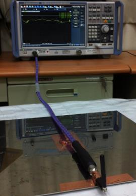
6 3. Antenna Characteristics 3.1 Testing Setup Antenna Straight Position a)in free space b)with 15*9cm c)with 30*30cm d)with 30*30cm Ground Plane Ground Plane Edge Ground Plane Center Antenna Bent 90 Position a)in free space b)with 15*9cm c)with 30*30cm d)with 30*30cm Ground Plane Ground Plane Edge Ground Plane Center Figure.1 Measurement environments SPE /C/W Page 6 of 39


7 3.2 Return Loss Figure2. Return loss of GW.05 antenna with straight position Figure3. Return loss of GW.05 antenna with bent position SPE /C/W Page 7 of 39
8 3.3 Efficiency Figure4. Efficiency of GW.05 antenna with straight position Figure5. Efficiency of GW.05 antenna with bent position SPE /C/W Page 8 of 39
9 3.4 Peak Gain Figure6. Peak gain of GW.05 antenna with straight position Figure7. Peak gain of GW.05 antenna with bent position SPE /C/W Page 9 of 39
10 3.5 Average Gain Figure8. Average gain of GW.05 with antenna straight position Figure9. Average gain of GW.05 antenna with bent position SPE /C/W Page 10 of 39


11 4. Antenna Radiation Patterns The antenna radiation patterns were measured in a CTIA certified ETS Anechoic Chamber. The measurement setup is shown below. Antenna with Straight Position In free space 15x9cm ground plane 30x30cm metal ground center 30x30cm metal ground edge SPE /C/W Page 11 of 39


12 Antenna Bent Position In free space 15x9cm ground plane 30x30cm metal ground center 30x30cm metal ground edge Figure.10. Testing Setup in ETS Anechoic Chamber SPE /C/W Page 12 of 39
13 4.1 2D Radiation Pattern (Straight position in free space) Plane Plane SPE /C/W Page 13 of 39
14 Plane Plane SPE /C/W Page 14 of 39
15 Plane Plane SPE /C/W Page 15 of 39
16 4.2 2D Radiation Pattern (Straight position with 15x9cm ground plane) Plane Plane SPE /C/W Page 16 of 39
17 Plane Plane SPE /C/W Page 17 of 39
18 Plane Plane SPE /C/W Page 18 of 39
19 4.3 2D Radiation Pattern (Straight position with 30x30cm ground plane edge) Plane Plane SPE /C/W Page 19 of 39
20 Plane Plane SPE /C/W Page 20 of 39
21 Plane Plane SPE /C/W Page 21 of 39
22 4.4 2D Radiation Pattern (Straight position with 30x30cm ground plane center) Plane Plane SPE /C/W Page 22 of 39
23 Plane Plane SPE /C/W Page 23 of 39
24 Plane Plane SPE /C/W Page 24 of 39
25 4.5 2D Radiation Pattern (Bent position in free space) Plane Plane SPE /C/W Page 25 of 39
26 Plane Plane SPE /C/W Page 26 of 39
27 Plane Plane SPE /C/W Page 27 of 39
28 4.6 2D Radiation Pattern (Bent position with 15x9cm ground plane) Plane Plane SPE /C/W Page 28 of 39
29 Plane Plane SPE /C/W Page 29 of 39
30 Plane Plane SPE /C/W Page 30 of 39
31 4.7 2D Radiation Pattern (Bent position with 30x30cm ground plane edge) Plane Plane SPE /C/W Page 31 of 39
32 Plane Plane SPE /C/W Page 32 of 39
33 Plane Plane SPE /C/W Page 33 of 39
34 4.8 2D Radiation Pattern (Bent position with 30*30cm ground plane center) Plane Plane SPE /C/W Page 34 of 39
35 Plane Plane SPE /C/W Page 35 of 39
36 Plane Plane SPE /C/W Page 36 of 39
37 5. Installation SPE /C/W Page 37 of 39
38 6. Mechanical Drawing SPE /C/W Page 38 of 39
39 7. Packaging 1 piece per small PE Bag, 100 small bags per big PE bag. SPE /C/W Page 39 of 39
SPECIFICATION. Product Name : 4G/3G/2G Cellular Hinged SMA(M) Mount Monopole
 Mount Monopole") SPECIFICATION Part No. : TG.9.113 Product Name : 4G/3G/2G Cellular Hinged SMA(M) Mount Monopole Feature : 7MHz to 38MHz LTE*/GSM/CDMA/HSPA/UMTS 7*/85/9/17/18/19/21/23/35/37 Rotatable hinge design for optimal
SPECIFICATION Part No. : TG.9.113 Product Name : 4G/3G/2G Cellular Hinged SMA(M) Mount Monopole Feature : 7MHz to 38MHz LTE*/GSM/CDMA/HSPA/UMTS 7*/85/9/17/18/19/21/23/35/37 Rotatable hinge design for optimal
SPECIFICATION. : 2 x 4G/3G/2G MIMO Antenna (698~960MHz, 1710~2170MHz,2300~2700MHz, MHz) MIMO1 antenna MIMO2 antenna
 MIMO1 antenna MIMO2 antenna") SPECIFICATION Part No. Product Name Feature : MA761.B.BICG.003 : Pantheon Antenna 4in1 MA761 Screw-Mount [Permanent Mount] 4G/3G/2G MIMO/ 2.4/5GHz MIMO : 2 x 4G/3G/2G MIMO Antenna (698~960MHz, 1710~2170MHz,2300~2700MHz,
SPECIFICATION Part No. Product Name Feature : MA761.B.BICG.003 : Pantheon Antenna 4in1 MA761 Screw-Mount [Permanent Mount] 4G/3G/2G MIMO/ 2.4/5GHz MIMO : 2 x 4G/3G/2G MIMO Antenna (698~960MHz, 1710~2170MHz,2300~2700MHz,
2J9547a CELLULAR/LTE MIMO and 2.4/5.0 GHz ISM MIMO Mast Mount
 Product Datasheet 2J9547a CELLULAR/LTE MIMO and 2.4/5. GHz ISM MIMO Mast Mount Key Features Cable 1 and 2: CELLULAR / LTE - 698-96 MHz - 171-217 MHz - 25-27 MHz Cable 3 and 4: 2.4/5. GHz ISM - 241-249
2J7068BGa-915 CELLULAR/LTE MIMO, 2.4/5.0 GHz ISM, 915 MHz ISM and GNSS
 Product Datasheet 2J768BGa-915 CELLULAR/LTE MIMO, 2.4/5. GHz ISM, 915 MHz ISM and GNSS Key Features Cable 1 and 2: CELLULAR / LTE Cable 3: 2.4/5. GHz ISM Cable 4: 915 MHz ISM Cable 5: GPS/GLONASS/QZSS/Galileo
2J4A50PCFa 2 4G LTE/3G/2G MIMO, 2 2.4/5.0 GHz ISM MIMO and GNSS Adhesive Mount
 Product Datasheet 2J4A5PCFa 2 4G LTE/3G/2G MIMO, 2 2.4/5. GHz ISM MIMO and GNSS Adhesive Mount Key Features Cable 1 and 2: 4G LTE/3G/2G - 698-96 MHz - 171-217 MHz - 25-27 MHz Cable 3 and 4: 2.4/5. GHz
MIMO LTE+MIMO Dual Band GHz+GNSS
 Tracking Solutions Embedded Antenna design GPS&Wireless solutions Provider MIMO Combo Antenna MODEL: AW-10 V1.0 2013-11-29 MIMO LTE+MIMO Dual Band 2.4-5.0GHz+GNSS Overview: The AW-10 is the multi-band
DATASHEET AMOTECH. Application
 Document Datasheet Type Chip Antenna Application ISM 868/915MHz Part No. AMAN9001ST05 Revision 4.0 DATASHEET Application ISM 868/915 MHz Features Monopole Structure Size (9.0*.0*1.mm ) Performance Optimizing
MA-203 Stingray GPS/Cellular Glassmount Covert Antenna
 MA-23 Stingray GPS/Cellular Glassmount Covert Antenna 3D view top view (this side faces the sky) underside view (this side faces the passenger) This is a combination high performance GPS and Quad-band
2.4 GHz. Description. Order Number. Specification. Value. Gain Impedance Type Polarization VSWR Frequency Weight Size Antenna Color
 2.4 GHz 2.5 GHz Dipole 2dBi Antenna for Reverse Polarity SMA ORDERING INFORMATION Order Number Description SPECIFICATIONS 1-11 2.4 GHz dipole antenna for reverse polarity SMA connector. Specification Gain
RDP-272+ DC to 2700 MHz (DC-950, MHz) The Big Deal Low insertion loss High isolation Miniature shielded package.
 The Big Deal Low insertion loss High isolation Miniature shielded package.") Surface Mount Diplexer 5Ω DC to 27 MHz (DC-95, 17-27 MHz) The Big Deal Low insertion loss High isolation Miniature shielded package CASE STYLE: CK65 Product Overview is a low-pass + high-pass combination
Surface Mount Diplexer 5Ω DC to 27 MHz (DC-95, 17-27 MHz) The Big Deal Low insertion loss High isolation Miniature shielded package CASE STYLE: CK65 Product Overview is a low-pass + high-pass combination
QM35. Cover. Output. A = Line Driver B = Line Driver (ABZ) /Open Collector (UVW) C = Dual Votage Line Driver (ABZ)/ Open Collector (UVW)
 /Open Collector (UVW) C = Dual Votage Line Driver (ABZ)/ Open Collector (UVW)") QM35 DESIGN FEATURES Bearingless modular design Low profile assembled height Resolutions up to 8192 lines per revolution 4, 6, 8 or 10 pole commutation Easy lock-n-twist assembly feature Through shaft
QM35 DESIGN FEATURES Bearingless modular design Low profile assembled height Resolutions up to 8192 lines per revolution 4, 6, 8 or 10 pole commutation Easy lock-n-twist assembly feature Through shaft
QML35. Cover. Voltage A = 5V (+/- 5%) B = 3.3V (+/- 5%)
 B = 3.3V (+/- 5%)") QML35 DESIGN FEATURES Bearingless modular design Low profile assembled height Resolutions up to 8192 lines per revolution 4, 6, 8 or 10 pole commutation Easy lock-n-twist assembly feature Through shaft
QML35 DESIGN FEATURES Bearingless modular design Low profile assembled height Resolutions up to 8192 lines per revolution 4, 6, 8 or 10 pole commutation Easy lock-n-twist assembly feature Through shaft
VAC, 50/60 Hz. -25 C to 65 C. Bluetooth Low Energy dBm. +5dBm. 1Mbit/s (2Mbit/s) 128 bit AES b/g/n
 128 bit AES b/g/n") SPECIFICATION SHEET BLUFI VER 1.3 HARDWARE SPECIFICATION AC Input AC Plugs 100-240 VAC, 50/60 Hz US type: NEMA 1-15 ungrounded (Type A) European: CEE 7/16 "Europlug" (Type C) British Standard BS 1363 (Type
SPECIFICATION SHEET BLUFI VER 1.3 HARDWARE SPECIFICATION AC Input AC Plugs 100-240 VAC, 50/60 Hz US type: NEMA 1-15 ungrounded (Type A) European: CEE 7/16 "Europlug" (Type C) British Standard BS 1363 (Type
 http://www.tekfun.com.tw/icm.php - Introduction - Tekfun Co., Ltd. has been manufacturing and exporting various Antennas and RF products since 1990. Taking advantage of our own professional Antenna Chamber,
Designing with an Inverted-F PCB Antenna
 Page 1 Application Note 5052 24 April 2008 Designing with an Inverted-F PCB Antenna For the EM250 and EM2 Platforms This document describes an Inverted-F PCB antenna designed by Ember for use with both
July Multilayer Diplexer. For MHz / MHz DPX202700DT-4062A1. 2.0x1.25mm [EIA 0805]* * Dimensions Code JIS[EIA]
![July Multilayer Diplexer. For MHz / MHz DPX202700DT-4062A1. 2.0x1.25mm [EIA 0805]* * Dimensions Code JIS[EIA]](/thumbs/82/86752617.jpg "July Multilayer Diplexer. For MHz / MHz DPX202700DT-4062A1. 2.0x1.25mm [EIA 0805]* * Dimensions Code JIS[EIA]") R F C o m p o n e n t s July 15 Multilayer Diplexer For 698-96MHz / 17-27MHz DPX27DT-462A1 2.x1.25mm [EIA 85]* * Dimensions Code JIS[EIA] Multilayer Diplexer For 698-96MHz / 17-27MHz Conformity to RoHS
R F C o m p o n e n t s July 15 Multilayer Diplexer For 698-96MHz / 17-27MHz DPX27DT-462A1 2.x1.25mm [EIA 85]* * Dimensions Code JIS[EIA] Multilayer Diplexer For 698-96MHz / 17-27MHz Conformity to RoHS
August Multilayer Diplexer. For MHz / MHz DPX165950DT-8144A1. 1.6x0.8mm [EIA 0603]* * Dimensions Code JIS[EIA]
![August Multilayer Diplexer. For MHz / MHz DPX165950DT-8144A1. 1.6x0.8mm [EIA 0603]* * Dimensions Code JIS[EIA]](/thumbs/93/111951709.jpg "August Multilayer Diplexer. For MHz / MHz DPX165950DT-8144A1. 1.6x0.8mm [EIA 0603]* * Dimensions Code JIS[EIA]") R F C o m p o n e n t s August 15 Multilayer Diplexer For 74-161MHz / -59MHz DPX1659DT-8144A1 1.6x.8mm [EIA 63]* * Dimensions Code JIS[EIA] Multilayer Diplexer For 74-161MHz / -59MHz Conformity to RoHS
R F C o m p o n e n t s August 15 Multilayer Diplexer For 74-161MHz / -59MHz DPX1659DT-8144A1 1.6x.8mm [EIA 63]* * Dimensions Code JIS[EIA] Multilayer Diplexer For 74-161MHz / -59MHz Conformity to RoHS
July Multilayer Diplexer. For MHz / MHz DPX162170DT-8122B1. 1.6x0.8mm [EIA 0603]* * Dimensions Code JIS[EIA]
![July Multilayer Diplexer. For MHz / MHz DPX162170DT-8122B1. 1.6x0.8mm [EIA 0603]* * Dimensions Code JIS[EIA]](/thumbs/73/69324547.jpg "July Multilayer Diplexer. For MHz / MHz DPX162170DT-8122B1. 1.6x0.8mm [EIA 0603]* * Dimensions Code JIS[EIA]") R F C o m p o n e n t s July 15 Multilayer Diplexer For 824-96MHz / 17-217MHz DPX16217DT-8122B1 1.6x.8mm [EIA 63]* * Dimensions Code JIS[EIA] Multilayer Diplexer For 824-96MHz / 17-217MHz Conformity to
R F C o m p o n e n t s July 15 Multilayer Diplexer For 824-96MHz / 17-217MHz DPX16217DT-8122B1 1.6x.8mm [EIA 63]* * Dimensions Code JIS[EIA] Multilayer Diplexer For 824-96MHz / 17-217MHz Conformity to
Insertion loss (db) TOP VIEW SIDE VIEW BOTTOM VIEW. 4x ± ± Orientation Marker Denotes Pin Location 4x 0.
 TOP VIEW SIDE VIEW BOTTOM VIEW. 4x ± ± Orientation Marker Denotes Pin Location 4x 0.") Model DC4759J52AHF Ultra Low Profile 85 2dB Directional Coupler Description The DC4759J52AHF is a low cost, low profile sub-miniature high performance 2 db directional coupler in an easy to use RoH compliant,
Model DC4759J52AHF Ultra Low Profile 85 2dB Directional Coupler Description The DC4759J52AHF is a low cost, low profile sub-miniature high performance 2 db directional coupler in an easy to use RoH compliant,
October Multilayer Diplexer. For MHz / MHz DPX165950DT-8030D1. 1.6x0.8mm [EIA 0603]* * Dimensions Code JIS[EIA]
![October Multilayer Diplexer. For MHz / MHz DPX165950DT-8030D1. 1.6x0.8mm [EIA 0603]* * Dimensions Code JIS[EIA]](/thumbs/82/85702705.jpg "October Multilayer Diplexer. For MHz / MHz DPX165950DT-8030D1. 1.6x0.8mm [EIA 0603]* * Dimensions Code JIS[EIA]") R F C o m p o n e n t s October 15 Multilayer Diplexer For 791-269MHz / 49-595MHz DPX16595DT-83D1 1.6x.8mm [EIA 63]* * Dimensions Code JIS[EIA] Multilayer Diplexer For 791-269MHz / 49-595MHz Conformity
R F C o m p o n e n t s October 15 Multilayer Diplexer For 791-269MHz / 49-595MHz DPX16595DT-83D1 1.6x.8mm [EIA 63]* * Dimensions Code JIS[EIA] Multilayer Diplexer For 791-269MHz / 49-595MHz Conformity
IEEE g (54Mbps) mini PCI Wireless LAN Module
 mini PCI Wireless LAN Module") XG-603 mpci WLAN Module IEEE 802.11g (54Mbps) mini PCI Wireless LAN Module Z comax Technologies, Inc. has released its new line of Air Runner wireless LAN mini-pci cards. The XG-603 is an IEEE 802.11g
XG-603 mpci WLAN Module IEEE 802.11g (54Mbps) mini PCI Wireless LAN Module Z comax Technologies, Inc. has released its new line of Air Runner wireless LAN mini-pci cards. The XG-603 is an IEEE 802.11g
3.6V / 2600mAh Primary Lithium x 0.85 (6 cm x 2.1 cm) 1.0 oz (28 gr) -25 C to 65 C. Bluetooth Low Energy dbm.
 1.0 oz (28 gr) -25 C to 65 C. Bluetooth Low Energy dbm.") SPECIFICATION SHEET ibeek VER 1.3 HARDWARE SPECIFICATION Battery Size Weight Temperature Range Bluetooth Type Bluetooth Sensitivity Bluetooth Max Power Output Bluetooth Antena Bluetooth Frequency Bluetooth
SPECIFICATION SHEET ibeek VER 1.3 HARDWARE SPECIFICATION Battery Size Weight Temperature Range Bluetooth Type Bluetooth Sensitivity Bluetooth Max Power Output Bluetooth Antena Bluetooth Frequency Bluetooth
Broadband covering primary wireless communications bands: Cellular, PCS, LTE, WiMAX, SATELLITE IF
 Flat Gain, High IP3 Monolithic Amplifier 50Ω 0.01 to 6 GHz The Big Deal Ceramic, Hermetically Sealed, Nitrogen filled Low profile case,.045 high Ultra Flat Gain Broadband High Dynamic Range without external
Evaluation Board User Guide UG-129
 Evaluation Board User Guide UG-129 One Technology Way P.O. Box 9106 Norwood, MA 02062-9106, U.S.A. Tel: 781.329.4700 Fax: 781.461.3113 www.analog.com Universal Evaluation Board for Dual High Speed Op Amps
Multilayer Band Pass Filters
 Multilayer Band Pass Filters For 5.GHz W-LAN DEA Series Type: DEA25425BT-29B2 (2..25.9mm) DEA25437BT-2 (2..25.9mm) DEA25375BT-254A (2..25.95mm) DEA25425BT-228A4 (2..25.95mm) Issue date: November 2 Conformity
3.6V / 2600mAh Primary Lithium x 0.85 (60mm x 21mm) 1.0 oz (28 gr) -30 C to +77 C. Bluetooth Low Energy dBm. +5dBm. 1Mbit/s / 2Mbit/s*
 1.0 oz (28 gr) -30 C to +77 C. Bluetooth Low Energy dBm. +5dBm. 1Mbit/s / 2Mbit/s*") SPECIFICATION SHEET BEEKs Industrial VER 1.6 HARDWARE SPECIFICATION Battery Size Weight Temperature Range Bluetooth Type Bluetooth Sensitivity Bluetooth Max Power Output Bluetooth Antenna Frequency Supported
SPECIFICATION SHEET BEEKs Industrial VER 1.6 HARDWARE SPECIFICATION Battery Size Weight Temperature Range Bluetooth Type Bluetooth Sensitivity Bluetooth Max Power Output Bluetooth Antenna Frequency Supported
Multilayer Band Pass Filters
 Multilayer Band Pass Filters For.GHz W-LAN/Bluetooth DEA Series Type: DEABT-6A (...mm) DEABT-6A (...7mm max.) DEABT-B (...8mm max.) DEABT-C (...9mm) DEABT-7A (...9mm) DEABT-8A (...9mm) DEABT-8A (...mm
V RM = 600 V, I F(AV) = 0.5 A, t rr = 100 ns Fast Recovery Diode. Description. Package. Features. Applications
 = 0.5 A, t rr = 100 ns Fast Recovery Diode. Description. Package. Features. Applications") V RM = 600 V, I F(AV) = 0.5 A, t rr = 100 ns Fast Recovery Diode Data Sheet Description The is a fast recovery diode of 600 V / 0.5 A. The maximum t rr of 100 ns is realized by optimizing a life-time control.
V RM = 600 V, I F(AV) = 0.5 A, t rr = 100 ns Fast Recovery Diode Data Sheet Description The is a fast recovery diode of 600 V / 0.5 A. The maximum t rr of 100 ns is realized by optimizing a life-time control.
Is Now Part of. To learn more about ON Semiconductor, please visit our website at
 Is Now Part of To learn more about ON emiconductor, please visit our website at www.onsemi.com Please note: As part of the airchild emiconductor integration, some of the airchild orderable part numbers
(loss < 1 db) (loss 3 db) (loss > 20 db) (loss > 40 db) typical frequency response DC (db) x σ RETURN LOSS. at RF level of 0 dbm
 (loss 3 db) (loss > 20 db) (loss > 40 db) typical frequency response DC (db) x σ RETURN LOSS. at RF level of 0 dbm") Coaxial Low Pass Filter 5Ω Maximum Ratings DC to 7 MHz Operating Temperature -55 C to 1 C Storage Temperature -55 C to 1 C RF Power Input.5W max. Permanent damage may occur if any of these limits are exceeded.
Coaxial Low Pass Filter 5Ω Maximum Ratings DC to 7 MHz Operating Temperature -55 C to 1 C Storage Temperature -55 C to 1 C RF Power Input.5W max. Permanent damage may occur if any of these limits are exceeded.
Monolithic Amplifier CMA-84+ Wideband, High Dynamic Range, Ceramic. DC to 7 GHz. The Big Deal
 Wideband, High Dynamic Range, Ceramic Monolithic Amplifier Ω DC to 7 GHz The Big Deal Ceramic, hermetically sealed, nitrogen filled Low profile case,.4 High IP3, +38 dbm High Gain, 24 db High POUT, +21
Configurations: Dimension (mm) IMCG ± ± ± ± IMCG ± ± ± ±
 IMCG ± ± ± ± IMCG ± ± ± ±") Chip s Multilayer Chip s For General Configurations: FEATURES To prevent EMI interference noises between. High Q and high reliability and ferrite material. Bead inductor for power energy storage or noise
Chip s Multilayer Chip s For General Configurations: FEATURES To prevent EMI interference noises between. High Q and high reliability and ferrite material. Bead inductor for power energy storage or noise
SERIES 2000 STICK ANTENNA
 Not Recommended for New designs RI-ANT-S01C, RI-ANT-S02C SERIES 2000 STICK ANTENNA SCBS851 DECEMBER 2002 REVISED DECEMBER 2005 FEATURES Best in Class Performance Through Patented HDX Technology IP 64+
Monolithic Amplifier CMA-162LN+ Ultra Low Noise, High IP to 1.6 GHz
 Ultra Low Noise, High IP3 Monolithic Amplifier 50Ω 0.7 to 1.6 GHz The Big Deal Ceramic, Hermetically Sealed, Nitrogen filled Low profile case,.045 high Ultra Low Noise Figure, 0.5 db High Gain, High IP3
V RM = 600 V, I F(AV) = 1.0 A General-Purpose Rectifier Diode. Description. Package. Features. Applications
 = 1.0 A General-Purpose Rectifier Diode. Description. Package. Features. Applications") V RM = 600 V, I F(AV) = 1.0 A General-Purpose Rectifier Diode Data Sheet Description The is a 600 V, 1.0 A general-purpose rectifier diode with low loss characteristics. This rectifier diode is for a commercial
V RM = 600 V, I F(AV) = 1.0 A General-Purpose Rectifier Diode Data Sheet Description The is a 600 V, 1.0 A general-purpose rectifier diode with low loss characteristics. This rectifier diode is for a commercial
Is Now Part of To learn more about ON Semiconductor, please visit our website at
 Is Now Part of To learn more about ON emiconductor, please visit our website at www.onsemi.com ON emiconductor and the ON emiconductor logo are trademarks of emiconductor Components Industries, LLC dba
FS8G - FS8M. 8 A Standard Recovery Surface Mount Rectifiers
 8G - 8M 8 A tandard Recovery urface Mount Rectifiers Description The 8G to 8M series offers breakthrough size and performance. It sinks 8 A DC forward current and provides up to 20 A surge current capability
THERMOPILE DETECTORS FOR MEASUREMENT. TPD 1T 0224, TPD 1T 0524, TPD 1T 0624 General-Purpose Thermopile
 THERMOPILE DETECTORS FOR MEASUREMENT THERMOPILE DETECTORS FOR MEASUREMENT TPD 1T 0224, TPD 1T 0524, TPD 1T 0624 General-Purpose Thermopile Applications This is our general-purpose range of thermopile detectors
PLC Splitter, Blockless Type 1xN, LIIN25 Features
 PLC Splitter, Blockless Type 1xN, LIIN25 Features Good channel-to-channel uniformity High reliability and small size Low Insertion loss and Low PDL Compact Design Good channel-to-channel uniformity Wide
Differential Return Loss for Clause 137 and Matched COM Package Parameters For Comments #92 and #93 Richard Mellitz, Samtec
 Differential Return Loss for Clause 137 and Matched COM Package Parameters For Comments #92 and #93 Richard Mellitz, Samtec March 2017 IEEE802.3 Plenary, Vancouver, BC, Canada 1 IEEE P802.3 50 Gb/s, 100
3M Pin Strip Header.100 and Straight and Right Angle, Solder Tail 2300 Series
 and Straight and Right Angle, Solder Tail 2300 Series One and two row versions Straight and right angle versions Tin lead or gold plating available Tapered tip does not cut the socket wipe during insertion,
Mysteries of DRA Modes Unresolved Issues for the Future
 Mysteries of DRA Modes Unresolved Issues for the Future Debatosh Guha Institute of Radio Physics and Electronics, University of Calcutta, India University College of Science and Technology 1914-214 1 On
AN021: RF MODULES RANGE CALCULATIONS AND TEST
 AN021: RF MODULES RANGE CALCULATIONS AND TEST We Make Embedded Wireless Easy to Use RF Modules Range Calculation and Test By T.A.Lunder and P.M.Evjen Keywords Definition of Link Budget, Link Margin, Antenna
Monolithic Amplifier CMA-83LN+ Low Noise, Wideband, High IP3. 50Ω 0.5 to 8.0 GHz
 Low Noise, Wideband, High IP3 Monolithic Amplifier 50Ω 0.5 to 8.0 GHz The Big Deal Ceramic, hermetically sealed, nitrogen filled Low profile case, 0.045 Flat gain over wideband Low noise figure, 1.3 db
K BAND SUPER LOW NOISE AMPLIFIER N-CHANNEL HJ-FET. Drop-In Replacement: CE3520K3. Part Number Order Number Package Quantity Marking Supplying Form
 FEATURES Super low noise figure and high associated gain HETERO JUNCTION FIELD EFFECT TRANSISTOR K BAND SUPER LOW NOISE AMPLIFIER N-CHANNEL HJ-FET NF = 0.75 db TYP., Ga = 10 db TYP. @ f = 20 GHz Micro-X
FSV10120V. Ultra-Low VF Schottky Rectifier, 10 A, 120 V
 Ultra-Low V chottky Rectifier, 10 A, 120 V eatures Ultra Low orward Voltage Drop Low Thermal Resistance Very Low Profile: Typical Height of 1.1 mm Trench chottky Technology Green Molding Compound as per
V RSM = 30 V, I F(AV) = 2.0 A Schottky Diode. Description. Package. Features. Applications (1) (2) (1) Cathode (2) Anode
 = 2.0 A Schottky Diode. Description. Package. Features. Applications (1) (2) (1) Cathode (2) Anode") V RSM = 30 V, I F(AV) = A Schottky Diode Data Sheet Description The is a 30 V, A Schottky diode with allowing improvements in V F and I R characteristics. These characteristic features contribute to improving
V RSM = 30 V, I F(AV) = A Schottky Diode Data Sheet Description The is a 30 V, A Schottky diode with allowing improvements in V F and I R characteristics. These characteristic features contribute to improving
SAW FILTER FOR RKE Murata part number :SAFBC315MSP0T00
 AUTOMOTIVE SAW FILTER FOR RKE Package Dimensions Top View Specification Item Nominal Center Frequency(fc) Specification -4 to +125 C typ. 315. MHz Dot Marking(φ.5) Bottom View (.1) 3.±.2 Q N (3) (4) (1).75±.2
 PACKAGE OPTION ADDENDUM www.ti.com 25-May-2018 PACKAGING INFORMATION Orderable Device Status (1) Package Type Package Drawing Pins Package Qty Eco Plan UC2638DW NRND SOIC DW 20 25 Green (RoHS UC2638DWG4
3M Polarized Boardmount Socket.100".100" Centerbump Polarization with Straight Solder Tails 8500 Series
 3M Polarized Boardmount Socket.100".100" Centerbump Polarization with Straight Solder Tails 8500 Series Centerbump polarization Mates with low profile shrouded headers Part number on each piece Optional
SC-70 Evaluation Board User Guide UG-112
 SC-70 Evaluation Board User Guide UG-112 One Technology Way P.O. Box 9106 Norwood, MA 02062-9106, U.S.A. Tel: 781.329.4700 Fax: 781.461.3113 www.analog.com Evaluation Board for Single, High Speed Op Amps
BLF7G20L-160P; BLF7G20LS-160P
 BLF7G20L-160P; BLF7G20LS-160P Rev. 01 22 June 2010 Objective data sheet 1. Product profile 1.1 General description 160 W LDMOS power transistor for base station applications at frequencies from 1800 MHz
SOT-23 Single Op Amp Evaluation Board User Guide UG-838
 SOT-23 Single Op Amp Evaluation Board User Guide One Technology Way P.O. Box 9106 Norwood, MA 02062-9106, U.S.A. Tel: 781.329.4700 Fax: 781.461.3113 www.analog.com Evaluation Board for Single, High Speed
DISCRETE SEMICONDUCTORS DATA SHEET
 DISCRETE SEMICONDUCTORS DATA SHEET book, halfpage M3D252 BGY687 600 MHz, 21.5 db gain push-pull amplifier Supersedes data of 1995 Sep 11 2001 Nov 08 FEATURES Excellent linearity Extremely low noise Silicon
Propagation Path Loss Measurements for Wireless Sensor Networks in Sand and Dust Storms
 Frontiers in Sensors (FS) Volume 4, 2016 doi: 10.14355/fs.2016.04.004 www.seipub.org/fs Propagation Path Loss Measurements for Wireless Sensor Networks in Sand and Dust Storms Hana Mujlid*, Ivica Kostanic
To request a full data sheet, please send an to:
 To request a full data sheet, please send an email to: display_contact@list.ti.com. PACKAGE OPTION ADDENDUM 11-Apr-2013 PACKAGING INFORMATION Orderable Device Status (1) Package Type Package Drawing Pins
APPLICATION FORM: Authorization for the installing, maintaining and operating of a VSAT network. REVENUE STAMP OF NAF. 10
 Authorization for the installing, maintaining and operating of a VSAT network. REVENUE STAMP OF NAF. 10 1 GENERAL INFORMATION The application for the authorization for installing, maintaining and operating
SRR4818A Series - Shielded Power Inductors
 *RoHS COMPLIANT & AEC APPROVED Features n Shielded construction n Inductance range: 1 to 47 µh n Heating current up to 5.1 A n AEC-Q2 qualified n RoHS compliant* and halogen free** Applications n Automotive
DISCONTINUED. 3M PC Card Header Single Slot, Low Profile, No Ejector, Standard Footprint. Physical. Electrical. Environmental. UL File No.
 PC Card Header Meets PCMCIA specifications Tapered header pins provide easy insertion High temperature plastic insulator Stand-off height options ESD clips and plastic pegs for secure hold-down See Regulatory
Case Material: Molded Plastic. UL Flammability Classification Low Reverse Leakage Current
 Pb 4A GLASS PASSIVATED BRIDGE RECTIFIER Features Mechanical Data Glass Passivated Die Construction Case: Rating to 1,000V PRV Case Material: Molded Plastic. UL Flammability Classification Low Reverse Leakage
EELE 5414 Wireless Communications. Chapter 4: Mobile Radio Propagation: Large-Scale Path Loss
 EELE 5414 Wireless Communications Chapter 4: Mobile Radio Propagation: Large-Scale Path Loss In the last lecture Outline Diffraction. Scattering. Practical link budget design. Log-distance model Log-normal
V RSM = 400 V, I F(AV) = 2.0 A General-Purpose Rectifier Diode. Description. Package. Features. Applications (1) (2) (1) Cathode (2) Anode
 = 2.0 A General-Purpose Rectifier Diode. Description. Package. Features. Applications (1) (2) (1) Cathode (2) Anode") V RSM = 400 V, I F(AV) = A General-Purpose Rectifier Diode Data Sheet Description The is a 400 V, A general-purpose rectifier diode with low loss characteristics. This rectifier diode is for a commercial
V RSM = 400 V, I F(AV) = A General-Purpose Rectifier Diode Data Sheet Description The is a 400 V, A general-purpose rectifier diode with low loss characteristics. This rectifier diode is for a commercial
PACKAGE OPTION ADDENDUM
 PACKAGE OPTION ADDENDUM www.ti.com 24-Aug-2018 PACKAGING INFORMATION Orderable Device Status (1) Package Type Package Drawing Pins Package Qty Eco Plan (2) Lead/Ball Finish (6) MSL Peak Temp (3) Op Temp
PHOTO DIODE NR6800 Series
 PHOTO DIODE NR6800 Series 80 m InGaAs AVALANCHE PHOTO DIODE FOR OTDR APPLICATIONS DESCRIPTION The NR6800 Series is an InGaAs avalanche photo diode, and can be used in OTDR systems. FEATURES Small dark
Type 778P/779P, Orange Drop, Polypropylene Film/Foil Capacitors
 Type 778P/779P Orange Drop 400 Volts A-C Polypropylene Film/Foil Capacitors Features Specifically designed for A-C voltage applications where corona free operation is required for high reliability. Extremely
Wireless Communications
 NETW701 Wireless Communications Dr. Wassim Alexan Winter 2018 Lecture 5 NETW705 Mobile Communication Networks Dr. Wassim Alexan Winter 2018 Lecture 5 Wassim Alexan 2 Outdoor Propagation Models Radio transmission
Radio Propagation Modelling
 Radio Propagation Modelling Ian Wassell and Yan Wu University of Cambridge Computer Laboratory Why is it needed? To predict coverage between nodes in a wireless network Path loss is different from environment
For a detailed datasheet and other design support tools, please contact
 This device is designed specifically to power Intel processors under a strict disclosure agreement with Intel Corporation. The end user must have a current CNDA in place with Intel Corporation to access
PACKAGE OPTION ADDENDUM
 PACKAGE OPTION ADDENDUM www.ti.com 15-Apr-2017 PACKAGING INFORMATION Orderable Device Status (1) Package Type Package Drawing Pins Package Qty Eco Plan (2) Lead/Ball Finish (6) MSL Peak Temp (3) Op Temp
TOSHIBA Field Effect Transistor Silicon N Channel MOS Type RFM07U7X
 RFMUX TOSHIBA Field Effect Transistor Silicon N Channel MOS Type RFMUX VHF- and UHF-band Amplifier Applications (Note)The TOSHIBA products listed in this document are intended for high frequency Power
SN54HCT08, SN74HCT08 QUADRUPLE 2-INPUT POSITIVE-AND GATES
 SN54HCT08, SN74HCT08 QUADRUPLE 2-INPUT POSITIVE-AND GATES SCLS063D NOVEMBER 1988 REVISED AUIGUST 2003 Operating Voltage Range of 4.5 V to 5.5 V Outputs Can Drive Up To 10 LSTTL Loads Low Power Consumption,
Statistical Analysis of On-body Radio Propagation Channel for Body-centric Wireless Communications
 374 PIERS Proceedings, Stockholm, Sweden, Aug. 12 15, 2013 Statistical Analysis of On-body Radio Propagation Channel for Body-centric Wireless Communications H. A. Rahim 1, F. Malek 1, N. Hisham 1, and
 The information provided on all ISP packages and pricing is correct at the time of publishing. Internet Service Providers may change packages and pricing at any time which is outside of Vumatel s control.
Recommended Land Pattern: [mm]
![Recommended Land Pattern: [mm]](/thumbs/73/68316164.jpg "Recommended Land Pattern: [mm]") Dimensions: [mm] Recommended Land Pattern: [mm] Electrical Properties: Properties Test conditions Value Unit Tol. 3 Inductance 10 khz/ 0.1 ma L. mh ±30% 1 4 Rated Current @ 70 C I R.75 A max. DC Resistance
Dimensions: [mm] Recommended Land Pattern: [mm] Electrical Properties: Properties Test conditions Value Unit Tol. 3 Inductance 10 khz/ 0.1 ma L. mh ±30% 1 4 Rated Current @ 70 C I R.75 A max. DC Resistance
description/ordering information
 SCLS079E MARCH 1984 REVISED MARCH 2004 Wide Operating Voltage Range of 2 V to 6 V Outputs Can Drive Up To 10 LSTTL Loads Low Power Consumption, 20-µA Max I CC Typical t pd = 7 ns ±4-mA Output Drive at
Specifications. 10 Year Limited Warranty. 1. IP65 Rated 2. Superior glare prevention and light quality 3. Best mounted at a range of 20 to 40 feet
 ATG s Helix High Bay is an evolution of commercial high bay lighting. The Helix High Bay is ideally deployed for use in distribution centers, manufacturing facilities, and large retail facilities with
3M Serial Advanced Technology Attachment (SATA) Connector Host Receptacle, Vertical and Right Angle, Std Height, Surface Mount Receptacle 5622 Series
 Connector Host Receptacle, Vertical and Right Angle, Std Height, Surface Mount Receptacle 5622 Series") M Serial Advanced Technology Attachment (SATA) Connector 22-position signal and power combination Input/ouput connector for backplane applications EMLB contacts for "hot swap" Blind mate polarization for
M Serial Advanced Technology Attachment (SATA) Connector 22-position signal and power combination Input/ouput connector for backplane applications EMLB contacts for "hot swap" Blind mate polarization for
RLB Series Radial Lead Inductors
 *RoHS COMPLIANT eatures n our types available n High rated current for high current circuits n Available in E12 series n RoHS compliant* Applications n Power supplies n DC/DC converters n General use RLB
BAS70-00-V to BAS70-06-V
 Small Signal Schottky Diodes, Single & Dual Features These diodes feature very low turn-on voltage and fast switching These devices are protected by a PN junction guard ring against excessive voltage,
GS500 Instruction manual
 MARINE SPEAKERS GS500 Instruction manual Introduction Congratulations on your purchase of the GME Marine Speakers. These speakers are designed to the highest level of quality and will offer you years of
Solid-Electrolyte TANTALEX Capacitors, Hermetically-Sealed, Axial-Lead
 Solid-Electrolyte TANTALEX Capacitors, Hermetically-Sealed, Axial-Lead PERFORMANCE CHARACTERISTICS Operating Temperature: -55 C to +125 C (above 85 C, voltage derating is required) Capacitance Tolerance:
SYMBOL TYPE NUMBER VALUE UNIT. Power dissipation at Tamb = 60 ºC 1.5 W. Non repetitive peak zener dissipation (t = 10ms) 40 W
 40 W") DO-204AL (DO-41) Voltage Power Dissipation 10 to 200 V 1.5 W Maximum Ratings and Electrical Characteristics at 25 C FEATURE Glass passivated chip junction Hiperectifier structure for high reliability Cavity-free
DO-204AL (DO-41) Voltage Power Dissipation 10 to 200 V 1.5 W Maximum Ratings and Electrical Characteristics at 25 C FEATURE Glass passivated chip junction Hiperectifier structure for high reliability Cavity-free
SRR4828A Series - Shielded Power Inductors
 *RoHS COMPLIANT & AEC APPROVED 22 Features Shielded construction Inductance range: 1.2 to 22 µh Heating current up to 5 A AEC-Q2 qualified RoHS compliant* and halogen free** SRRA Series - Shielded Power
Project: IEEE P Working Group for Wireless Personal Area Networks (WPANs)
") Project: IEEE P802.15 Working Group for Wireless Personal Area Networks (WPANs) Title: Channel Model for Intra-Device Communications Date Submitted: 15 January 2016 Source: Alexander Fricke, Thomas Kürner,
Project: IEEE P802.15 Working Group for Wireless Personal Area Networks (WPANs) Title: Channel Model for Intra-Device Communications Date Submitted: 15 January 2016 Source: Alexander Fricke, Thomas Kürner,
3M Serial Advanced Technology Attachment (SATA) Connector
 Connector") M Serial Advanced Technology Attachment (SATA) Connector 22-position signal and power combination Input/ouput connector for backplane applications EMLB contacts for "hot swap" Blind mate polarization for
M Serial Advanced Technology Attachment (SATA) Connector 22-position signal and power combination Input/ouput connector for backplane applications EMLB contacts for "hot swap" Blind mate polarization for
SN54HCT04, SN74HCT04 HEX INVERTERS
 SN54HCT04, SN74HCT04 HEX INVERTERS SCLS042D JULY 1986 REVISED JULY 2003 Operating Voltage Range of 4.5 V to 5.5 V Outputs Can Drive Up To 10 LSTTL Loads Low Power Consumption, 20-µA Max I CC Typical t
VHF variable capacitance diode
 Rev. 4 6 September 2011 Product data sheet 1. Product profile 1.1 General description The is a variable capacitance diode, fabricated in planar technology and encapsulated in the SOD323 (SC-76) very small
An Assessment of Technical Risks in PV Investments
 Solar Bankability Brussels (BE) An Assessment of Technical Risks in PV Investments Ioannis Thomas Theologitis (SolarPower Europe) Funded by the Horizon 2020 Framework Programme of the European Union Project
Features rugged welded case, hermetic other standard and custom PLP models available with wide selection of fco
 Plug-In Low Pass Filter 5Ω Maximum Ratings DC to 15 MHz Operating Temperature -55 C to 1 C Storage Temperature -55 C to 1 C RF Power Input.5W max. Permanent damage may occur if any of these limits are
Features rugged welded case, hermetic other standard and custom PLP models available with wide selection of fco
 Plug-In Low Pass Filter 5Ω Maximum Ratings DC to 1 MHz Operating Temperature -55 C to 1 C Storage Temperature -55 C to 1 C RF Power Input.5W max. Permanent damage may occur if any of these limits are exceeded.
3M Mini Serial Attached SCSI (minisas) Connector Assembly Internal Right Angle Combo Connector
 Connector Assembly Internal Right Angle Combo Connector") M Mini Serial Attached SCSI (minisas) Connector Assembly 8AB6 Series Capable of 6 Gbps per channel data rate Combination receptacle/shell assembly to facilitate board assembly Available with pre-positioning
M Mini Serial Attached SCSI (minisas) Connector Assembly 8AB6 Series Capable of 6 Gbps per channel data rate Combination receptacle/shell assembly to facilitate board assembly Available with pre-positioning
8508A Reference Multimeter Extended Specifications
 8508A Reference Multimeter Extended Specifications General Specifications Specifications Power Voltage 115 V Setting...100 V to 10 V rms designed for additional voltage fluctuations 10 %. 30 V Setting...00
50 V, 3 A PNP low VCEsat (BISS) transistor
 transistor") Rev. 6 28 June 2011 Product data sheet 1. Product profile 1.1 General description PNP low V CEsat Breakthrough In Small Signal (BISS) transistor in a small SOT457 (SC-74) Surface-Mounted Device (SMD) plastic
Rev. 6 28 June 2011 Product data sheet 1. Product profile 1.1 General description PNP low V CEsat Breakthrough In Small Signal (BISS) transistor in a small SOT457 (SC-74) Surface-Mounted Device (SMD) plastic
Real-Time Path Loss Modelling for a More Robust Wireless Performance
 Real-Time Path Loss Modelling for a More Robust Wireless Performance Q. Braet 1, D. Plets 1, W. Joseph 1, L. Martens 1 1 Information Technology Department, Ghent University/iMinds Gaston Crommenlaan 8,
Product Specification Qualification Test Report
 PS 92 / DMI SM APC Low IL / 9/211 DIAMOND Test & Calibration Laboratory STS 333 / SCS 11 Product Specification Qualification Test Report DMI SM APC Low IL DIAMOND SA Via dei Patrizi 5 CH-6616 LOSONE Tel.
Type AHA SMT Aluminum Electrolytic Capacitors -55 C to +105 C - Long Life
 SMT Aluminum Electrolytic Capacitors -55 C to +5 C - Long Life Long Life Filtering, Bypassing, Power Supply Decoupling Type AHA Capacitors deliver twice the life of many SMT aluminum capacitor types, and
3M Molded Assembly 2 mm x 2 mm 2M Series
 M Molded Assembly 2 mm x 2 mm 2M Series Available in multiple sizes Sockets mate with standard 2 mm 2 mm headers and plugs Molded-in strain relief See Regulatory Information Appendix (RIA) for chemical
TOSHIBA Transistor Silicon NPN Epitaxial Type TMBT3904
 TOSHIBA Transistor Silicon NPN Epitaxial Type TMBT3904 Audio Frequency General Purpose Amplifier Applications High voltage and high current : VCEO = 50 V, IC = 150 ma (max) Complementary to TMBT3906 Absolute
Link Budget Calculation. Ermanno Pietrosemoli Marco Zennaro
 Link Budget Calculation Ermanno Pietrosemoli Marco Zennaro Goals To be able to calculate how far we can go with the equipment we have To understand why we need high masts for long links To learn about
SN54LS266, SN74LS266 QUADRUPLE 2-INPUT EXCLUSIVE-NOR GATES WITH OPEN-COLLECTOR OUTPUTS
 SN54LS266, SN74LS266 QUADRUPLE 2-INPUT EXCLUSIVE-NOR GATES WITH OPEN-COLLECTOR OUTPUTS SDLS151 DECEMBER 1972 REVISED MARCH 1988 PRODUCTION DATA information is current as of publication date. Products conform